Digital i/o – Measurement Computing eZ-TOMAS version 7.1.x User Manual
Page 46
eZ-TOMAS & eZ-TOMAS Remote
887591
Edit Menu 3-20
Digital I/O…
Edit Menu
Hardware Panel
The top panel of the Digital I/O Configuration Window
is the Hardware panel.
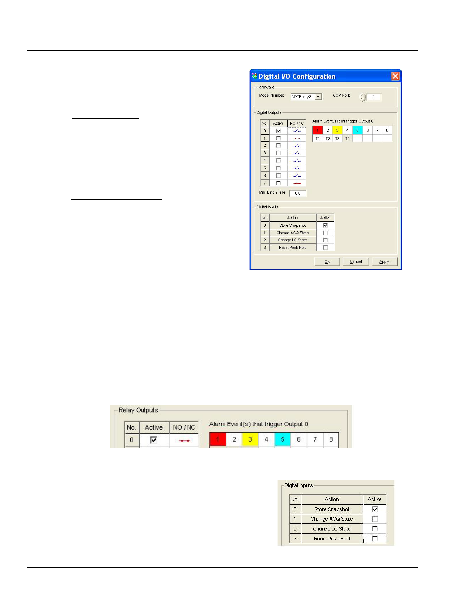
Digital I/O Configuration
For NDT Relay Modules
For
:
(1) An NDTRelay must be connected as indicated in
separate NDTRelay documentation.
(2) The applicable COM Port must be identified.
Select the RS232 COM (serial) Port to which the
output Relay module is connected
640, 650, and 652 Analyzers
Relay Outputs Panel
:
For these 600 series analyzers, the Digital outputs are
accessed via a 9-pin connector on the rear panel. Refer to
the associated product’s user manual for a pinout and
additional details. The manuals are located on the
Dynamic Signal Analysis CD in Adobe PDF format.
Relay outputs can be used to communicate Alarm Status to external devices. Up to 8 relay outputs are supported.
You must indicate, by checkmark, if a relay output is to be active. For an “active” relay, the normal state is either
Normally Open (NO) or Normally Closed (NC). In the preceding figure, only Relay Output 0 is “Active.”
When you click on one of the cells associated with a relay output, the “Alarm Events” that will trigger it appear to
the right of the output’s switch graphic. In the preceding figure we see the events that will trigger Relay Output 0.
When any of the defined Alarm Events are True, the relay will be in the state other than indicated in the NO/NC
column. For example, in the following figure Output Relay 0 is normally closed; thus the relay will open when
(a) Input Channel 1 is in Red Alarm Condition, or (b) Input Channel 3 is in Yellow Alarm Condition, or
(c) Input Channel 5 is in Cyan Alarm Condition.
Output Relay 0, Active, Normally Closed –
Shown set to Open on Alarm Conditions on Channels 1, 3, or 5
Digital Inputs Panel
Digital Inputs can be used to trigger eZ-TOMAS Actions. Each
supported action is assigned to specific Digital Input. For
example, in the figure at the right, Store Snapshot is assigned to
Digital Input 0. This means that the Store Snapshot action will
occur when Digital Input 0 changes state. Note: Digital Inputs are
available in NDTRelay2 [not NDTRelay1].
Store Snapshot Selected for Digital Input 0