Changing parameters on distance measuring sensors, Blindzone, Foreground suppression – Microsonic LCA-2 User Manual
Page 18: Selected detection range, Hanging parameters on distance measuring sensors
Page 18 of 51
Changing parameters on distance measuring sensors
C
HANGING PARAMETERS ON DISTANCE MEASURING SENSORS
Depending on the connected sensor (or according to the loaded sensor file) the input mask may
vary in its appearance. All changes which you make in the input mask are only temporarily stored in the
PC. Subsequently these new settings have to be be transferred to the sensor and / or be stored
permanently on the hard disc of your PC.
All general parameters can be set on switching sensors as well on analogue ultrasonic sensors.
The numeric values have to be input in mm and can be edited by keyboard.
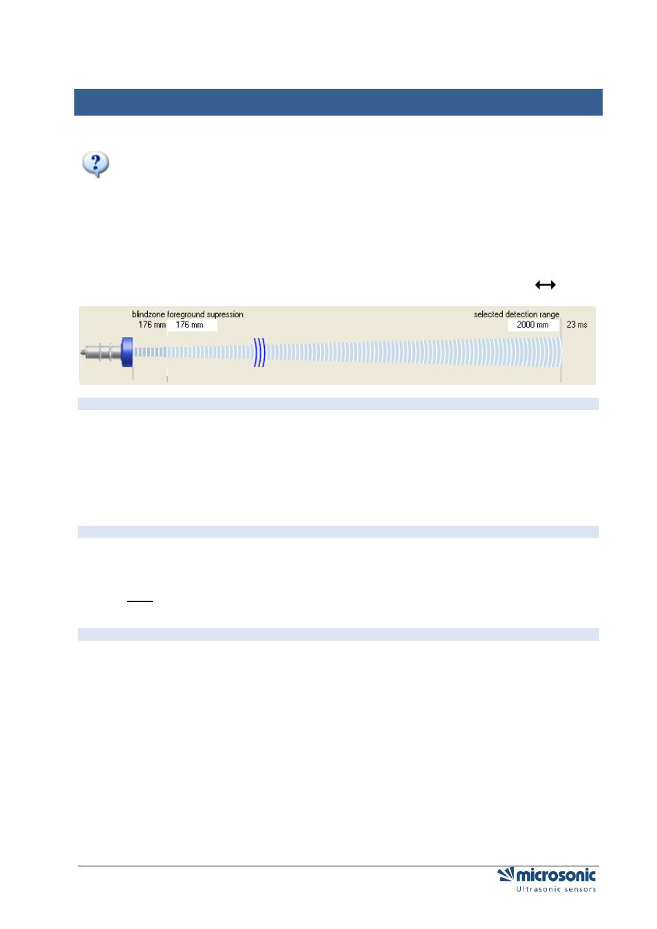
Additional the values of foreground suppression, switching distances, hysteresis points and window
margins can be changed by clicking and dragging the edge point (mouse pointer changes to
) .
B
LINDZONE
Since the ultrasonic sensor uses the same transducer element for both sending and receiving, the sensor
can-not start to read in echo signals before the oscillations of the strong sending pulse have calmed
down. This results in a blind zone which is typical for an ultrasonic sensor. The usable measurement
range begins right after the blind zone. The target distance should not be less than the blind zone, as this
may result in mismeasurements. The size of the blind zone varies with the different maximum detection
ranges of different models; the blind zone is sensor-immanent and cannot be influenced by the user.
F
OREGROUND SUPPRESSION
The foreground suppression represents an artificial enlargement of the blind zone, i.e. the measurement
range begins after the value of the foreground suppression instead of the blind zone. All echo signals,
which arrive between sensor and foreground suppression, are ignored. You can use this feature to
suppress small unwanted targets, which are located in the vicinity of the sensor.
S
ELECTED DETECTION RANGE
The selected detection range determines the maximum distance that can be measured. Using the default
set-tings the selected detection range is set to the maximum detection range of a sensor type. The
maximum detection range is the recommended - physically reasonable - detection range, up to which the
sensor can be used (assuming good reflection properties of the target object). The nominal detection
range, which is indicated in the technical data sheets of microsonic, represents on the other hand the
typical detection range where the sensor still functions according to its technical specifications - even on
reflectors with critical reflection properties (functional reserve).
The selected detection range takes effect on the repetition rate of sensor measurements. The time for a
single ultrasonic measurement, resulting from the selected detection range, is displayed above the
correspondent input field. If you decrease the selected detection range you will increase the measurement
repetition rate of the sensor. Please notice however that values below the nominal detection range of the
specific sensor type might affect the sensor function due to double reflections. Normally there is no need
to select a value for the selected detection range other than given by the default settings.