Table 4a: port a serial cable pin-outs, Table 4b: port b serial cable pin-outs, Table 4a a – NavCom SF-2110 Rev.C User Manual
Page 34
Advertising
SF-2110 User Guide – Rev. C
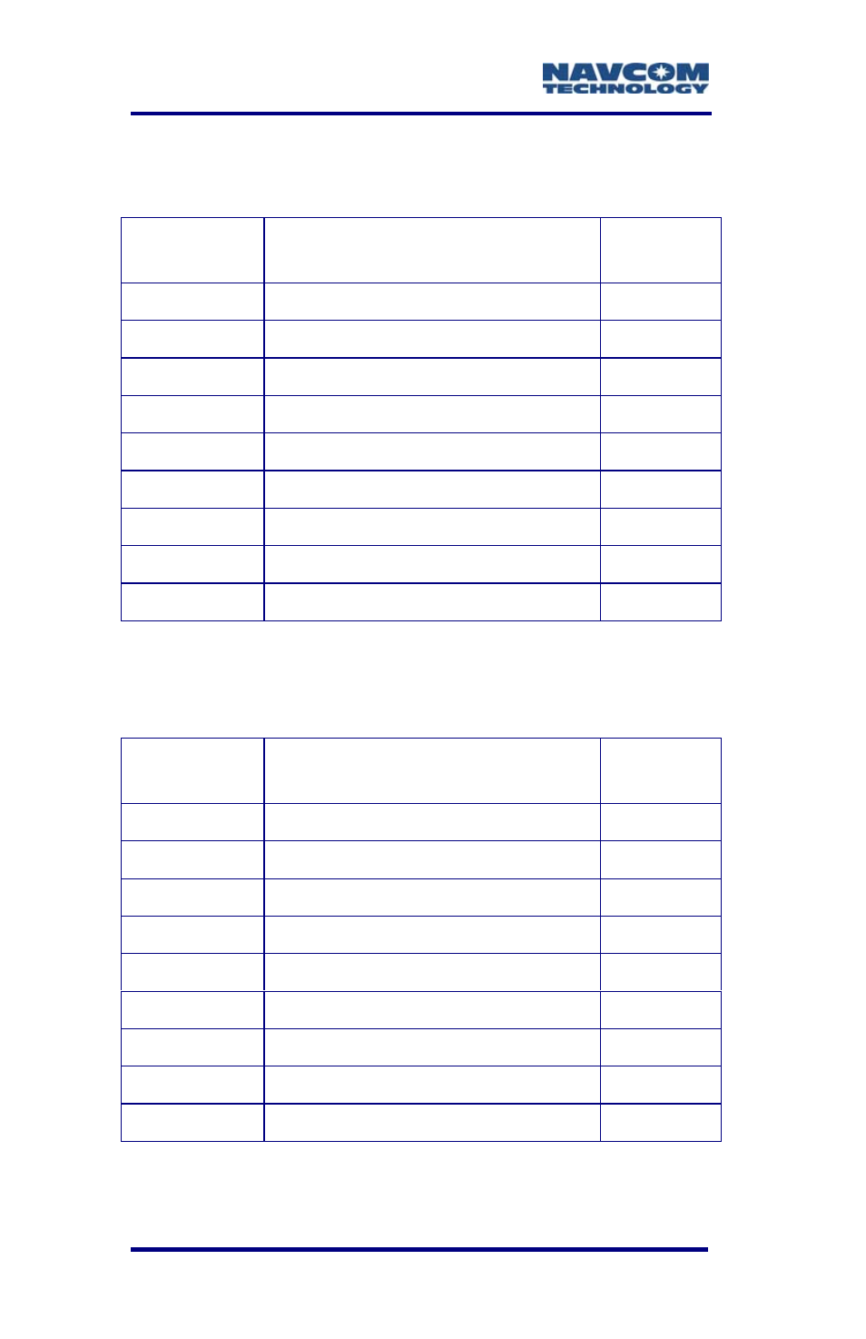
Table 4A: Port A Serial Cable Pin-Outs
(P/N 94-310260-3006LF)
Positronic
Pins
Signal Nomenclature
[DCE w/respect to DB9]
DB9S
Pins
1 Not
connected
-
2 Not
connected
-
3 *1PPS
8
4
RXD RS-232
3
5
TXD RS-232
2
6 Not
connected
7
7 Not
connected
-
8 Not
connected
-
9 GND
5
Table 4B: Port B Serial Cable Pin-Outs
(P/N 94-310260-3006LF)
Positronic
Pins
Signal Nomenclature
[DCE w/respect to DB9]
DB9S
Pins
1 Not
connected
-
2 Not
connected
-
3 RD+
RS-422
8
4
RXD RS-232 / RD- RS-422
3
5
TXD RS-232 / TD- RS-422
2
6 TD+
RS-422
7
7 Not
connected
-
8 Not
connected
-
9 GND
5
2-32
* Consult Release Notes on the NavCom web site for availability.
Advertising
This manual is related to the following products: