Chapter 3 installation, Standard antenna, Chapter 3 – NavCom SF-2110 Rev.C User Manual
Page 43: Installation, Figure 13: standard gps/l-band antenna
SF-2110 User Guide – Rev. C
Chapter 3 .................................Installation
This chapter provides guidance on hardware
installation for optimum performance.
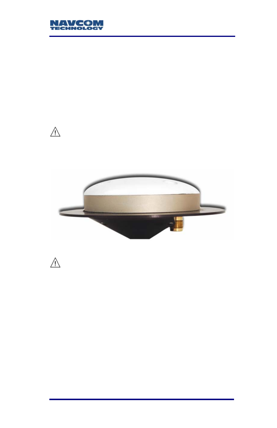
Standard Antenna
The 5/8 inch BSW threaded antenna mount has a
depth of 16mm (0.63 inch).
The BSW insert is secured in-place with an
adhesive, and its removal will change the
shock and vibration sustainability
characteristics of the antenna mount.
Figure 13: Standard GPS/L-band Antenna
Do not loosen or remove the Phillips screws
on the base of the antenna for mounting
purposes. This will VOID the warranty and
compromise the environmental seal of the
antenna, leading to internal damage.
9 Antenna placement is critical to good system
performance. Avoid antenna shading by buildings,
rooftop structures, foliage, hills/mountains, etc.
9 Locate the antenna where it has a clear view of
the sky, to an elevation angle of 7º if possible.
Obstructions below 15º elevation generally are
not a problem, though this is dependent on
satellite availability for the local region.
* Consult Release Notes on the NavCom web site for availability.
3-41