4 data link output lines, 3 what the leds mean, Table 4 below – Nevion UDC-3G-XMUX4+ User Manual
Page 13
UDC-3G-XMUX4+
Rev. C
nevion.com | 13
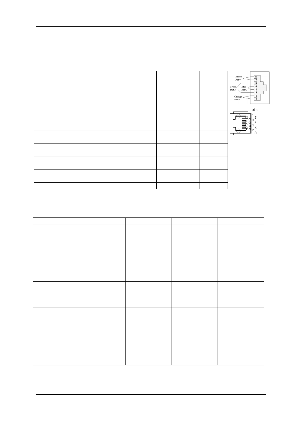
2.2.4 Data link output lines
The UDC-3G-XMUX4 has one pair of data output lines. Together they form an RS422 output.
The data is de-embedded from one of the embedded audio channels. These data must of
course have been embedded by another module upstream. See Table 4 below for the pin-
out.
GPI name
Function
Pin #
Mode
Direction
Status
General error status for the
module. Will also activate at
firmware upgrades, when
the module is not.
Pin 1 Inverted Open
Collector
(open is alarm)
Output
GPI 1
GPI default scaling select.
Least significant bit.
Pin 2 TTL, 0V =
active level
Input
GPI 2
GPI default scaling select
Pin 3 TTL, 0V =
active level
Input
DATA link
output
RS422+
Pin 4 RS422
Output
DATA link
output
RS422-
Pin 5 RS422
Output
GPI 4
GPI default scaling select.
Most significant bit.
Pin 6 TTL, 0V =
active level
Input
GPI 3
GPI default scaling select.
Pin 7 TTL, 0V =
active level
Input
Ground
0 volt pin
Pin 8 0V.
Table 4: The TP45 (8pin modular jack) in detail
2.3 What the LEDs mean
Table 5: LED states and what they mean
Red LED
Orange LED
Green LED
No light
Card status
PTC fuse has
been triggered
or FPGA
programming
has failed
Module has not
been
programmed, or
RESET and
OVR DIPS are
both on, or
module is
loading
firmware.
Module is OK
Module has no
power
SDI input
status
Video signal
absent.
Video signal
present but card
unable to lock
VCXO
Video signal
present and
locked
Module has not
been
programmed
Sync input
status
Sync signal
absent
Sync signal
present but card
unable to lock
VCXO
B&B or Tri-level
sync in lock
Module has not
been
programmed
Audio input
status
No audio
embedded in
incoming video
One, two or
three audio
groups
embedded in
incoming video
4 audio groups
embedded in
incoming video
Module has not
been
programmed