3 data path, 4 video input selection – Nevion UDC-3G-XMUX4+ User Manual
Page 25
UDC-3G-XMUX4+
Rev. C
nevion.com | 25
3.3 Data path
The 3G/HD/SD-SDI input is selected from either optical or electrical input and equalized, re-
clocked and de-serialized and transferred to a processing unit called an FPGA. In the FPGA
the signal is first sent through a de-glitcher that cleans up small single-line errors that might
appear for instance due to switching. In the de-glitcher the ancillary data to be remapped in
the output video stream is also de-embedded. The video is then passed over to the audio de-
embedder that de-embeds all audio from the video.
The 16 audio channels coming from the de-embedder are bundled in pairs and sent to an
audio buffer. The audio is fetched from the audio buffer according to a user specified delay
and sent to an Audio cross point. The audio from the Audio cross point can be any pair of
audio channels de-embedded from the incoming video stream, AES inputs, an internal 1 kHz
sine or an internal silence generator. The silence generator (labelled mute) produces valid
audio, just silent. These audio generators can be set as fallback when no valid audio is
available, but the options also exist to turn the AES outputs completely off or set the delete
flag for embedded audio. From the cross point outputs each channel pair enters an Audio
Processing Block, where the paired channels may be shuffled. After the audio processing
block the audio enters the Audio Embedder.
After the audio de-embedder, the active area of the video is sent through the scaler blocks
and to a frame buffer. The video is then fetched from the frame buffer with the user specified
delay and sent to a Video processing block followed by an EDH processing block. After the
EDH block the video and audio is embedded according to the user settings and the video is
sent from the FPGA to a serializer that re-clocks the data and outputs the SDI to a buffered
output switch.
The buffered output switch is a 2x2 crosspoint
with input 1 being the equalized and re-
clocked input (non-processed) and input 2 being the output of the video processing. The two
outputs are sent to two paired (non-inverting and inverting) outputs.
There are also 4 I/O ports for AES. These can be setup to be either inputs, outputs or a mix.
The outputs are taken from the Audio cross point and can be any stereo pair of audio
channels embedded on the incoming video stream, AES inputs (if any), the internal 1 kHz
sine generator or the internal silence generator. The inputs are routed through optional audio
delays and sample rate converters before they enter the audio cross point matrix.
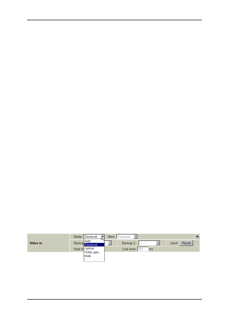
3.4 Video input selection
The UDC-3G-XMUX4 has one electrical and one (optional) optical input. The input can be
chosen either by an automatic selection with priorities and rule of switching, or by manual
selection. When the input selection is done manually by selecting one of the inputs from the
Mode menu, no fallback is available to other sources are available, but there will be a frame
freeze for as long as the input is gone.
Manual selection mode
Figure 15: Multicon GYDA view of electrical input selected manually