9 gas piping, Gas piping – Nortec GS Series User Manual
Page 12
9 | GS Series Installation
Gas Piping
Installation of piping must be in accordance with local codes, and ANSI Z233.1, “National Fuel Gas Code,” in
the United States or CSA B149.1 installation codes in Canada.
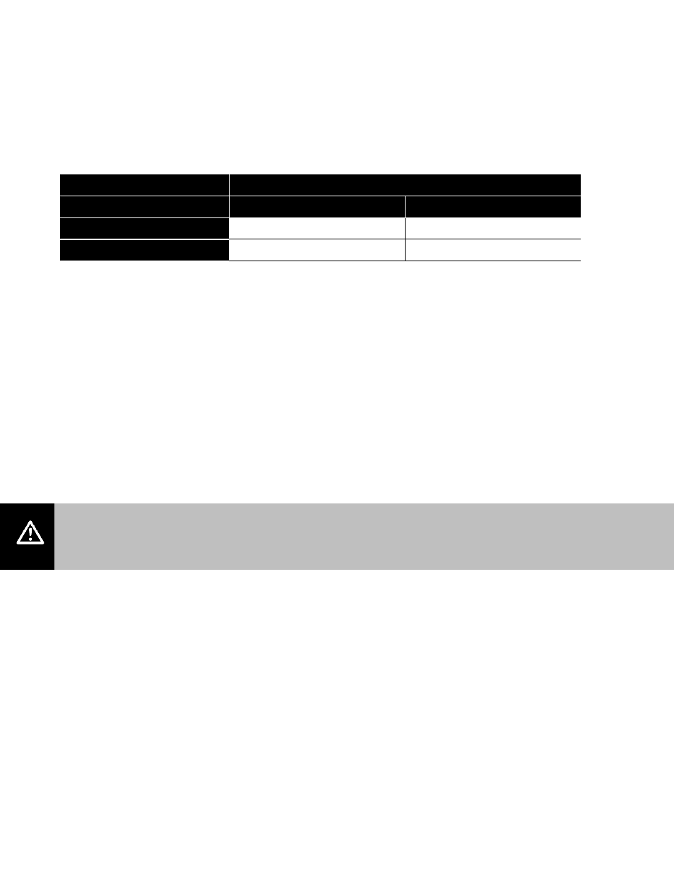
The following table indicates the maximum and minimum allowable gas pressures for the gas humidifier.
Table 3: Max & Min Gas Pressure
Inches w.c.
Gas
Min
Max
Natural
4.5
9.0
Propane
9.0
13.0
The gas inlet pipe size to the appliance is:
½”
NPT for GS 100
¾”
NPT for GS 200
1” NPT for GS 300 / 400
1 ¼” NPT for GS 500 / 600
Provide an adequate size gas supply line.
In all installations, a certified manual shut off valve, located outside the cabinet, must be installed. When
black iron gas pipe is used, a sediment trap must be located ahead of the humidifier gas controls. See
Figure 5: Gas Connection.
Leak test all gas connections external to the humidifier, using a commercial soap solution made to detect
leaks. Bubbles indicate gas leakage. Seal all leaks before placing the humidifier in operation.
Warning:
Never use an open flame to check for gas leaks. If a leak does exist, a fire or explosion could occur,
resulting in damage, injury or death.
The appliance and its individual shut-off valve must be disconnected from the gas supply piping system
during any pressure testing of that system at test pressures equal to or greater than 14” w.c. (3.5 kPa).
The appliance must be isolated from the gas supply piping system by closing its individual manual shut-off
valve during any pressure testing of the gas supply piping system at test pressures equal or less than 14”
w.c. (3.5 kPa).
Dissipate test pressure from the gas supply line before re-opening the manual shut off valve to the
appliance.