Removal and installation of the combustion blower, Gas valve replacement – Nortec GS Series User Manual
Page 53
GS Series Installation | 50
Removal and Installation Of The Combustion Blower
Shut off electrical power and gas supply to the humidifier.
Remove the right side service access door.
Disconnect all wiring to the combustion blower, gas valve and air proving switch (note the connector
assignment).
Undo the coupling on the flexible gas hose and disconnect the gas hose from the gas valve.
Undo the 2 screws that mount the gas valve/air inlet assembly to the blower and remove the assembly.
Undo the 2 screws of the fan-board mounting bracket (if present) and remove bracket, leaving electronic
board and igniter jump start module(s) attached.
Undo the 4 nuts on the blower outlet and remove blower.
Reverse the sequence above to install the new combustion blower. Inspect and replace any gaskets that
may be damaged. When mounting the gas valve/air inlet assembly to the combustion blower, ensure that
the cork gasket is properly oriented or gas flow through the valve will be impeded.
Leak test the gas train before re-commissioning the humidifier.
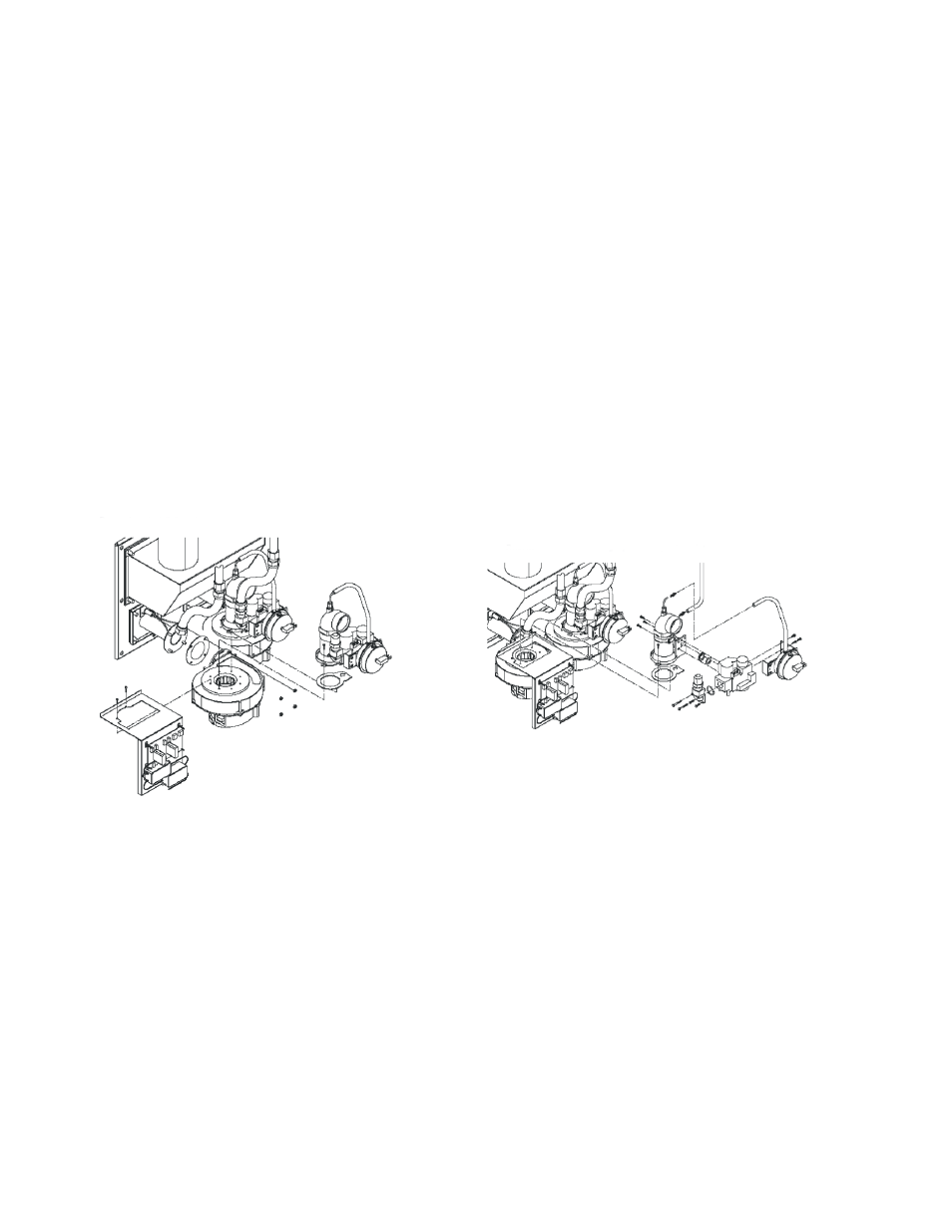
Figure 34: Combustion Blower Replacement
Figure 35: Gas Valve Replacement
Gas Valve Replacement
Shut off electrical power and gas supply to the humidifier.
Remove the right side service access door.
Disconnect all wiring to the gas valve and air proving switch (note the connector assignment).
Undo the coupling on the flexible gas hose and disconnect the gas hose from the gas valve.
Remove the hoses from the air proving switch (note the connection layout).
Undo the 2 screws that mount the gas valve/air inlet assembly to the blower and remove the assembly.
Undo the 4 screws and remove the gas pipe connection from the inlet of the gas pressure regulating valve.
Undo the 3 screws that hold the air inlet venturi to the gas valve. Remove the rubber grommet and brass
orifice mounted in the outlet of the gas valve.