System setup and operations – RGBLink VSP 516S User Manual User Manual
Page 91
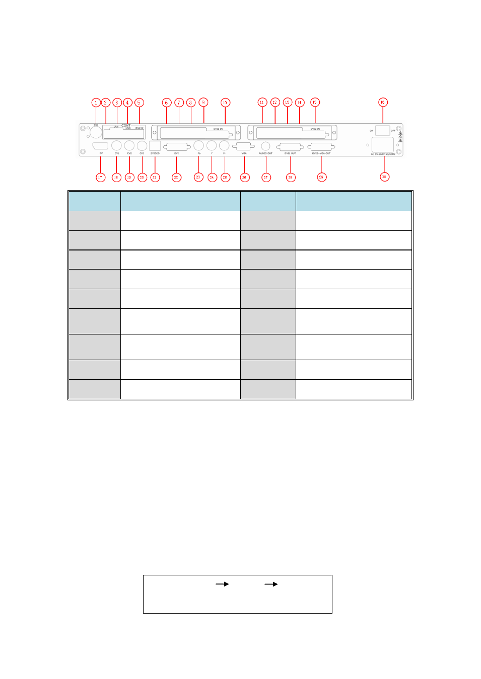
6. System Setup and Operations
Interface and Input Signal Option
VSP 516S User Manual 91
VSP 516S back panel with two sending cards.
NO
INTERFACE
NO
INTERFACE
1
3G-SDI input BNC CVBS port 18~20
CVBS Input BNC port
2
Dial the code switch
21
S-Video DIN 4
3.6.7.11.12
10/100M Interface RJ45
22
DVI Input DVI-I
4.9.14
USB Interface
23~25
YPbPr Input
5
RS232 Interface
26
VGA Input DB15 port
8.13
Power supply port of
Sending Card
27
Audio Output
10.15
DVI input port of
sending card
28
DVI Output DVI-I
16
Switch
29
DVI+VGA DVI-I Output
17
Displayport Input
30
Power IEC-3 port
28. DVI1 output , use for connecting the sending card of LED display .
VSP516S support resolution format as following:
800×600×60, 1024×768×60, 1024×768×75, 1280×720×50, 1280×720×60,
1280×768×60, 1280×800×60, 1280×1024×60, 1360×768×60,
1366×768×60, 1400×1050×60, 1440×800×60, 1440×900×60,
1600×1200×60, 1680×1050×60, 1920×1080×50, 1920×1080×60,
1920×1120×60, 1920×1200×60, 2048×1152×60, 2560×812×60,
2560×816×60.
Note
Same as MENU OUTPUT FORMAT