Displaying circuit element status in a node, The possible csus are numbered 1 to 28 – Verilink Access Manager 2000 (896-502037-001) Product Manual User Manual
Page 279
Displaying circuit element status in a node
Access Manager 2000 User Manual
8-9
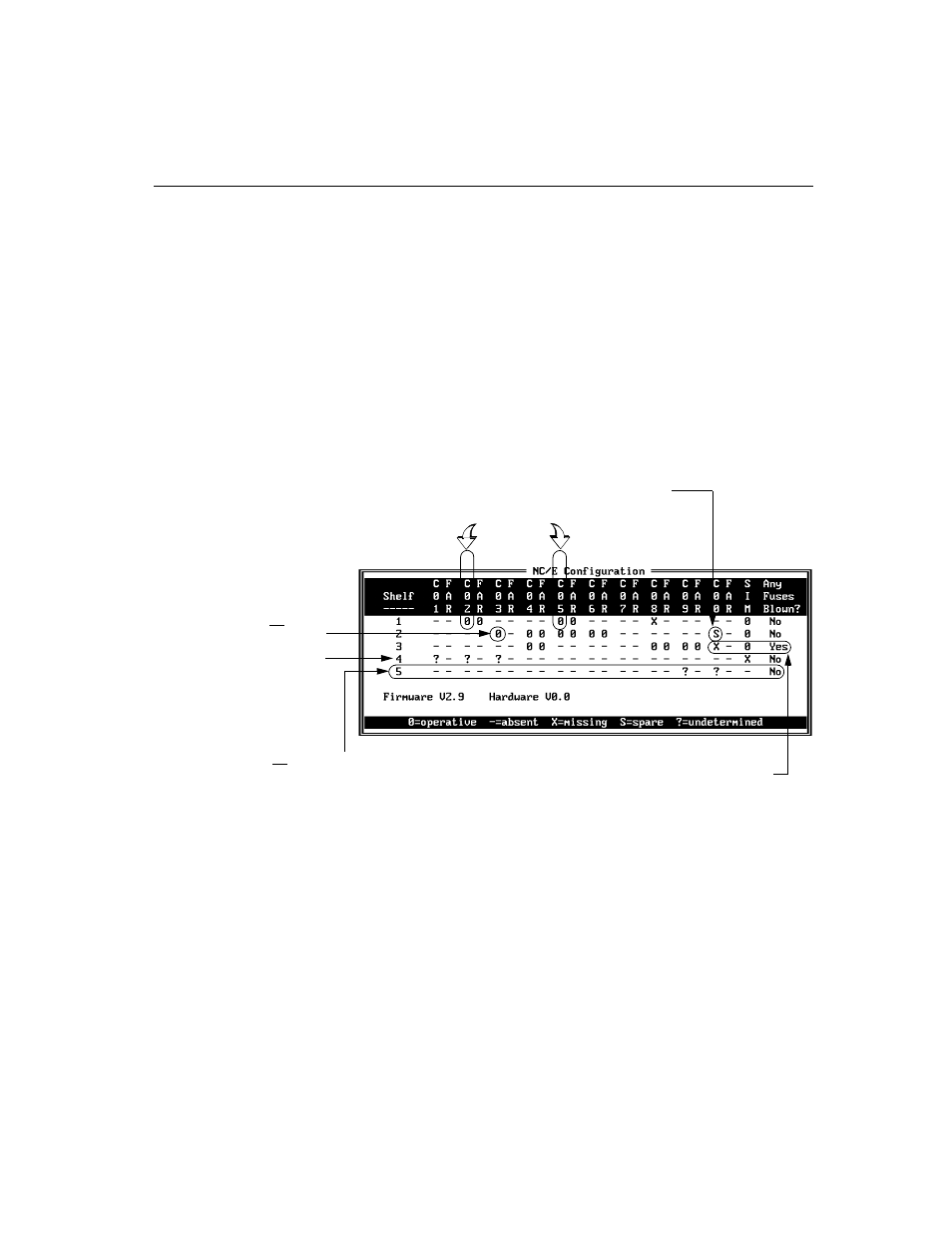
Each shelf has one SIM shelf controller and up to ten 4016-R CSU circuit
elements.
The CSUs are designated by C01 to C10, reading from left to right.
Paired with each of these CSUs is a far-end CSU, designated by a column
labeled “FAR”.
For a 551VST ML List 1 or List 2 node, the status of the 28 possible near-
end CSUs are on one line with the corresponding far-end CSU status on
the next line. The fuse status is not shown, and the power supply status
appears on the right side.
Specifically, the display example shows the following:
For the 551VST ML List 1 and 2, the following differences exist in the
NC/E Configuration Display and SIM Configuration Display screens:
■
The possible CSUs are numbered 1 to 28.
■
The Far-End CSU indicator is on the line below the near-end.
■
The right side of the screen has a Power Supply A and B (551VST
List 1/A or List 1/B), or A, B, C, and D (for 551VST List 2) status
indication.
On Shelf 1, CSUs #2 and #5 are
•
equipped
•
configured
•
receiving signals from the far end
On Shelf 2, CSU #3 is not
receiving a signal from the far end.
On Shelf 2, CSU #10
is a spare.
On Shelf 3, CSU #10 is missing. The
blown fuse status is YES, indicating
that CSU #10 has a blown 5V fuse.
On Shelf 4, the shelf is equipped
and the SIM is missing or has failed.
The status of the first 3 CSUs is
undetermined.
On Shelf 5, the shelf is not equipped (SIM is absent).
•
CSUs #1 to #8 are not installed in the database
•
CSUs # 9 and #10 are undetermined. If they are physically
absent, set the
Installed and Operational
configuration option to
NO
.