Hardware configuration and testing, Controls and indicators, 3 hardware configuration – Verilink PRISM 3002 (34-00277) Product Manual User Manual
Page 19: And testing, Controls and indicators -1, Ardware, Onfiguration, Esting
3
H
ARDWARE
C
ONFIGURATION
AND
T
ESTING
This chapter contains general operating instructions for the Verilink PRISM 3002
front panel. The unit may be controlled manually using both the front panel
buttons and the configuration switches. Chapter 4, Terminal Configuration and
Testing, discusses the firmware controlled terminal interface program, which
provides the maximum amount of control.
Controls and
Indicators
The NMS address and supervisory (SUPV) port bit rate are set using the dual in-line
package (DIP) switches located on the front panel of the unit (see Figure 3-1). A
removable configuration guide (45-00121) is included in the back of this manual.
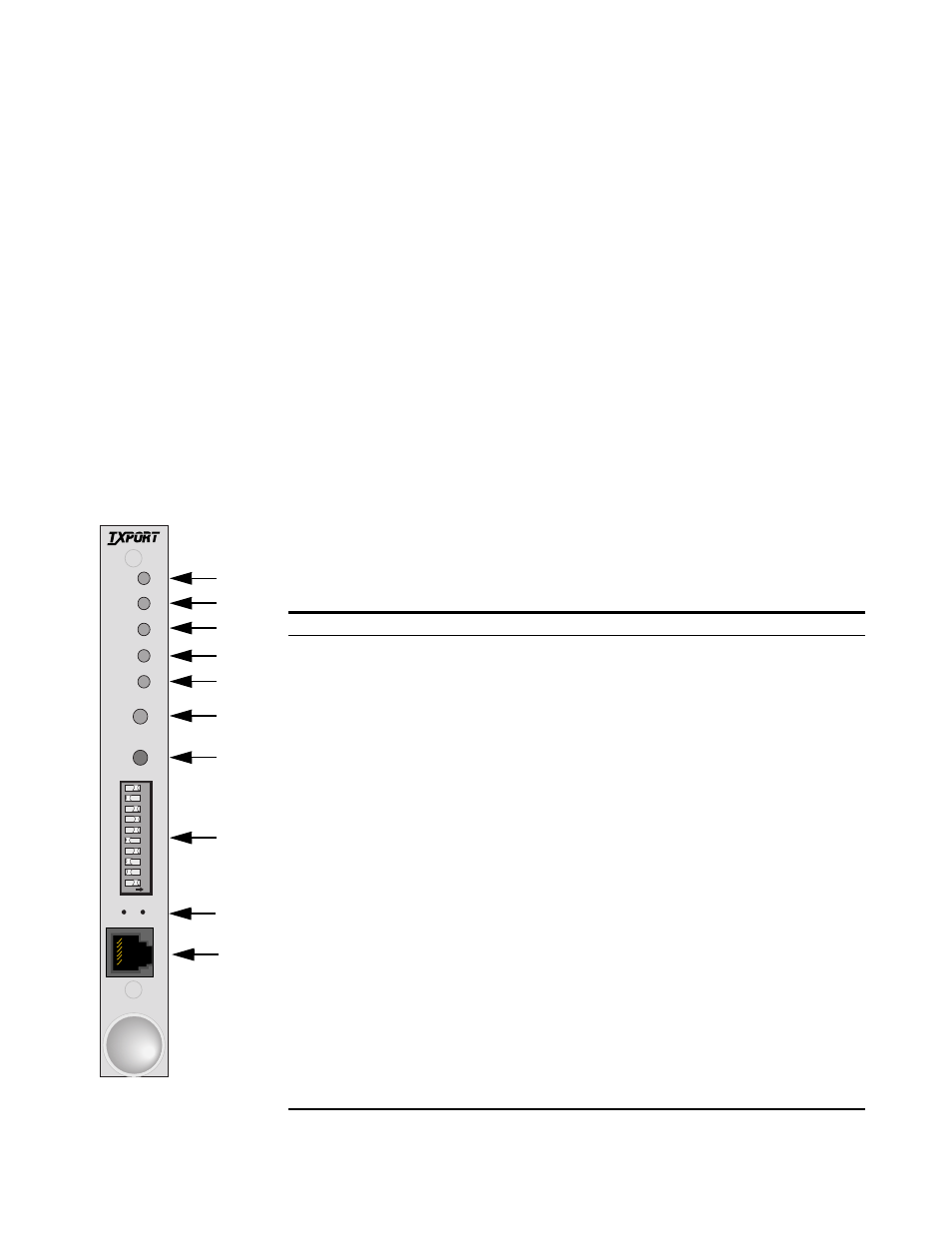
Figure 3-1 depicts the front panel which has five LED indicators, two control
buttons, a 10-position DIP switch, two viewing holes, the SUPV port, and the
extractor/card lock. Table 3-1 references these controls and indicators.
Table 3-1 PRISM 3002 Controls and Indicators
Index
Feature
Function/Description
1 PWR
(green)
This LED lights continuously when power is applied to the unit.
2 ALM
( red)
This LED lights continuously when the unit is in an active alarm condition.
3
TST
(3-color)
Flashing Green: The unit is transmitting loop code.
Solid Green:
BERT is on with no errors or the unit is in clear test.
Red:
BERT is on and receiving errors.
Amber:
The unit is looped.
4
DBU
This indicator is on when the unit is in dial backup mode.
5 NET
(3 - color)
Green:
The unit is in frame sync.
Amber: The unit is receiving a yellow alarm from the far end.
Red:
The unit is out of frame sync and/or has loss of signal.
6
TST
When this button is pushed once, the unit transmits five seconds of in-band LLB code
(see Figure 3-3 on page 3 - 3) out to the network and performs a T1 NET BERT. The
indicator blinks green during transmission of the loop code.
If the TST button is pushed again, the unit transmits five seconds of in-band loop down
code and returns to normal operating mode. The TST indicator then turns off.
7
LP
When this momentary push button is pushed once, the unit activates a line loopback,
looping the network receive data back to the network, and looping the data from the
DTE ports back to the DTE. The TST indicator is amber while the unit is looped. If
pushed again, the unit clears the loop and turns off the TST indicator.
8
See NMS Address and SUPV Port Bit Rate on page 3 -2.
9
These two small, recessed LEDs indicate supervisory and network manager port activity.
10
SUPV
See SUPV Port Bit Rate, Supervisory Port, and Upgrading Software on page 3 -3. For
the pinout, see Data Port on page 2 -3.
11
Extractor/ Card Lock
1
PWR
ALM
TST
DBU
NET
TST
LP
10
9
8
7
6
5
4
3
2
1
ON
T
R
A
N
S
P
O
R
T
®
10
1
S
U
P
V
3002
Figure 3-1 3002 Front
2
3
4
5
6
7
8
10
9