Installation – Grass Valley Performer SD User Manual
Page 116
2-84
Section 2 —
Installation
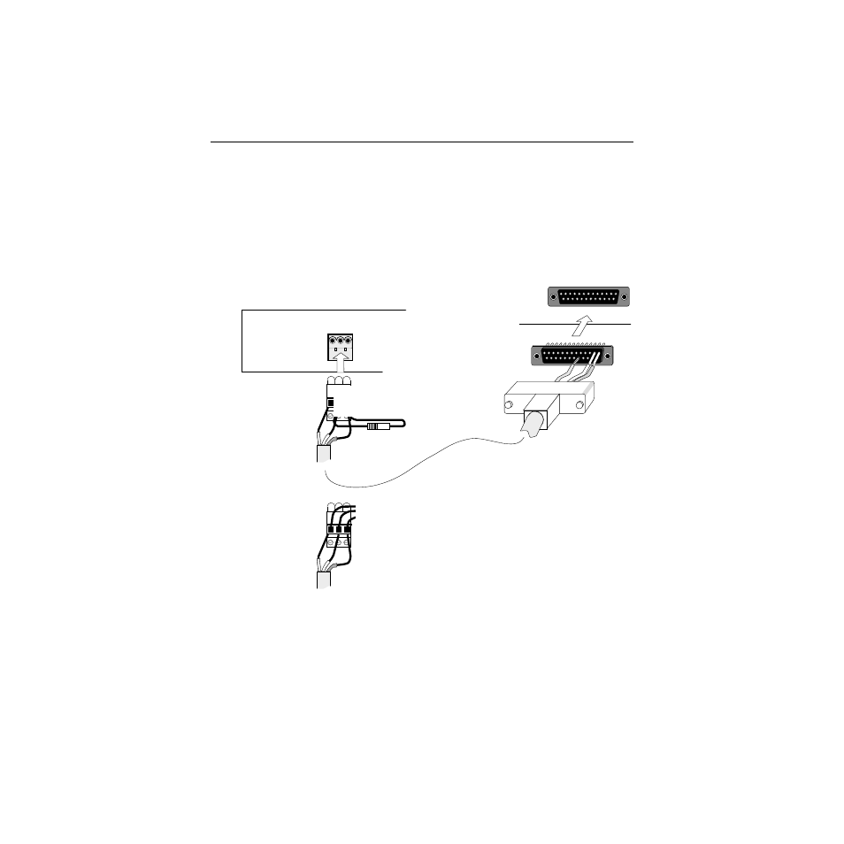
RS485 Bus
Use three-conductor wire (Belden 8451 or equivalent) to connect
the control panel(s) and the routing switcher(s). The cable may
loop from device to device (as many as 32) but must be terminated
at each end device using a 150-ohm resistor between the (+) and
(–) data lines. Control panel and switcher cable end connectors are
provided.
COMMUNICATIONS BUS
S
_
+
J2
REMOTE
At Switcher:
1. Connect (+) to pin 1
2. Connect (–) to pin 2.
3. Connect (S) to pin 18.
4. To extend bus, use OPTION
connector. Looping Cable option must
be installed. Wire units in parallel using
only the pins listed above. Pin 4 is wired
from master units to associated slave
units.
Control Panel or Serial Interface
Switcher
At Control Panel:
1. Strip insulation
back 3/8 inch.
2. Insert wire end
in hole above
screw.
3. Tighten screw
to secure.
4. To extend bus,
simply parallel
wiring to
existing
connector:
150-ohm terminating resistor
from (+) to (–). Install only if
panel is an end device on bus.
To other
control panels
or serial
interface.