Remote connector cabling, Remote connector cabling -33, Caution – Grass Valley Performer SD User Manual
Page 65: Installation reference
2-33
Installation Reference
Remote Connector Cabling
The 25-pin, female D REMOTE connector provides a point of
connection for:
■
Optional remote control panel (RS485)
■
RS232, RS422 interface
■
External Vertical Interval Strobe
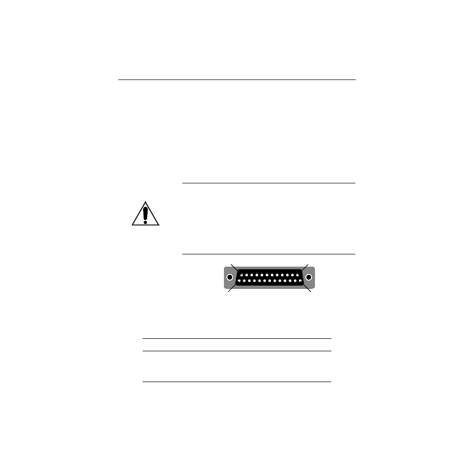
Connector pin numbering is illustrated below. Table 2-4 lists the
signal-to-pin number correlation.
CAUTION
If you are adding your own control device, using RS422 or RS485
control, you may need to construct a connecting cable.
Both RS422 and RS485 control require terminating resistors as
described in Removing/Replacing Terminating Resistors
later in this section. When cabling, be sure the terminating
resistor is installed at the end of the RS422 or RS485 bus.
Table 2-4. REMOTE Connector Pin Assignments
Signal
Pin
VA (bit A of 4-bit binary video status
13
VB (bit B of 4-bit binary video status
25
VC (bit C of 4-bit binary video status)
24
REMOTE
13
12
11
10
9
8
7
6
5
4
3
2
1
2524
2322
2120
1918
1716
1514
1
13
14
25