Ground terminal – Yaskawa FSP Short Form User Manual
Page 28
FSP Amplifier Short Form Installation Guide
Wiring
•
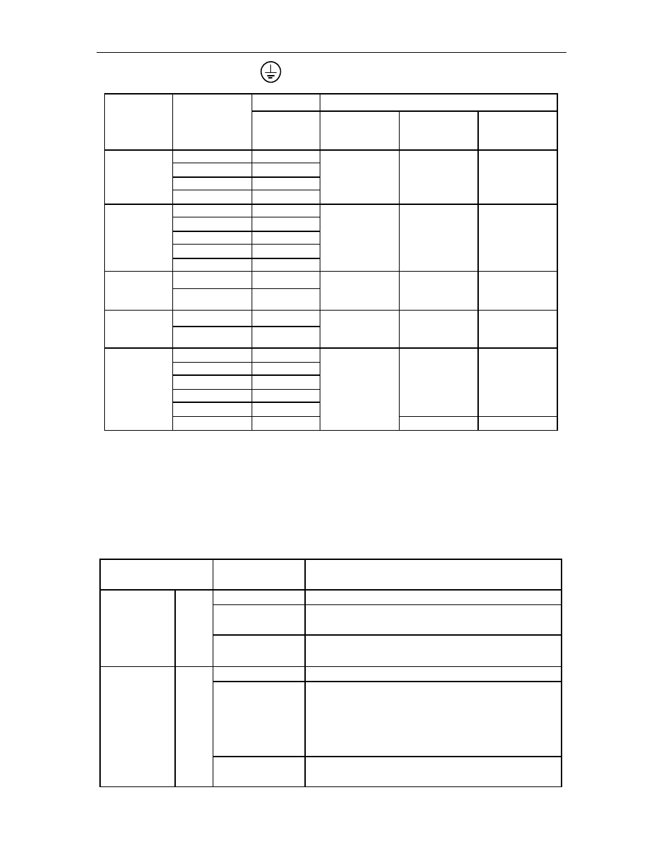
Ground Terminal
Model Ground
Terminal
Main
Circuit
Power
Supply
Capacity
(kW)
FSP-
Wire Type &
Size
(mm
2
)
Terminal
Screw
Size
Tightening
Torque
(N·m)
0.03 A3B*
0.05 A5B*
0.10 01B*
Single-
phase
100V
0.20 02B*
HIV 2.0 or
larger
M4
1.2 to 1.4
0.03 A3A*
0.05 A5A*
0.10 01A*
0.20 02A*
Single-
phase
200V
0.40 04A*
HIV 2.0 or
larger
M4
1.2 to 1.4
0.75 08A*
Single-
28
phase
220V
1.50 15A*
HIV 2.0 or
larger
M4
1.2 to 1.4
2.00 20A*
Three-
phase
200V
3.00 30A*
HIV 2.0 or
larger
M4
1.2 to 1.4
0.50 05D*
1.00 10D*
1.50 15D*
2.00 20D*
3.00 30D*
M4
Three-
1.2 to 1.4
HIV 2.0 or
larger
phase
400V
5.00 50D*
M5
1.6 to 2.4
• Signal Line Wire Sizes
The following table shows appropriate cables for CN1 and CN2 FSP Amplifier
connectors.
Wire sizes were selected for three cables per bundle at 40ºC ambient temperature
with the rated current.
Connector Name
and Signal
Item S pecification
Cable
Twisted-pair or shielded twisted-pair wire.
Applicable
wire
AWG24 (0.2 mm
2
), AWG26 (0.12 mm
2
),
AWG28 (0.08 mm
2
), AWG30 (0.05 mm
2
).
Control I/O
Signal
Connector
CN1
Finished cable
dimension
Ø 16.0 mm (Ø 0.63 in) MAX.
Cable
Shielded twisted-pair wire.
Applicable
wire
AWG 24 (0.2 mm
2
), AWG 26 (0.12 mm
2
),
AWG 28 (0.08 mm
2
), AWG 30 (0.05 mm
2
).
Use AWG 22 (0.33 mm
2
) for encoder power supply and
AWG 26 (0.12 mm
2
) for other signals.
These conditions permit wiring distances up to 20 m
(65.6 ft).
PG Signal
Connector
CN2
Finished cable
dimension
Ø 6.8 mm (Ø 0.27 in) MAX.