5 installation procedure – Yaskawa AC Drive V1000-Series Option SI-M3/V CompoNet User Manual
Page 19
5 Installation Procedure
YASKAWA ELECTRIC TOBP C730600 54A V1000 Option CompoNet Installation Manual
19
2.
The remaining installation steps differ based on drive model. Find the drive model
number on the drive nameplate and refer to the step indicated in
your model number.
Table 6 Installation Steps Based on Drive Model
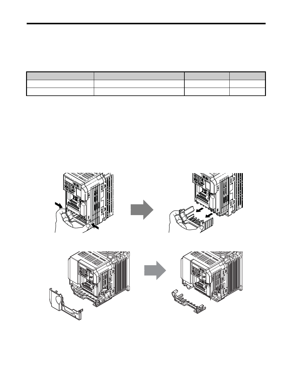
3.
For IP20/Open-Chassis models CIMR-V
A
B, Remove the bottom cover of
the drive by applying pressure to the tabs on each side of the bottom cover. Pull the
bottom cover away from the drive while pushing in on the tabs to release the cover
from the drive. Refer to
for details.
Refer to
for drive models CIMR-V
BA0006B to BA0018B, 2A0008B to
2A0069B, and 4A0001B to 4A0038B, which require removing the terminal cover
prior to removing the bottom cover.
Figure 5
Figure 5 Remove the Bottom Cover on an IP20/Open-Chassis Drive
(Models CIMR-V BA0001B to BA0003B and 2A0001B to 2A0006B)
Figure 6
Figure 6 Remove the Terminal Cover and Bottom Cover on an IP20/Open-Chassis Drive
(Models CIMR-V BA0006B to BA0018B; 2A0008B to 2A0069B; 4A0001B to 4A0038B)
Enclosure Type
Drive Model
Steps to Follow
Page
IP20/Open-Chassis
CIMR-V A B
,
IP20/NEMA Type 1
<1> Installing the option on an IP20/NEMA Type 1 enclosure drive voids NEMA Type 1 protection while maintaining
IP20 conformity
<2> After performing each step, proceed to step
CIMR-V A F