5 installation procedure, Connection diagram – Yaskawa AC Drive V1000-Series Option SI-M3/V CompoNet User Manual
Page 26
5 Installation Procedure
26
YASKAWA ELECTRIC TOBP C730600 54A V1000 Option CompoNet Installation Manual
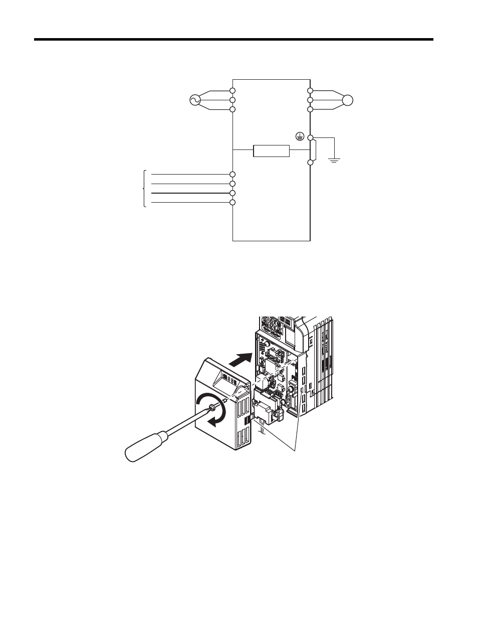
Connection Diagram
Figure 18
Figure 18 Wiring Diagram
<1> The ground wire provided in the option shipping package must be connected during
installation.
14.
Attach the option cover by aligning the tabs with the mounting holes, seat the front
cover into place, and tighten the screw on the front.
Figure 19
Figure 19 Attach the Option Cover
Note: Take proper precautions when wiring the option so that the front covers will easily fit back onto
the drive. Make sure no cables are pinched between the front covers and the drive when
replacing the covers.
Note: A replacement safety label is provided when using the drive in areas that may require displaying
warning information in Japanese or Chinese. This label can be placed over the English and
French warnings on the option cover.
15.
Set drive parameters in
for proper option performance.
V1000
SI-M3/V
M
U
V
W
R
BS+
BDH
BDL
BS-
S
T
CN5
FE
<1>
CompoNet Master
or
Relay Terminal Block
CompoNet Cable
Motor
Power
(Red)
(White)
(Blue)
(Black)
Line up tabs