Terminal cn1, Option led display – Yaskawa V1000-Series Option SI-EP3/V PROFINET User Manual
Page 11
4 Option Components
YASKAWA SIEP YEACOM 06A V1000 Option PROFINET SI-EP3/V Technical Manual
11
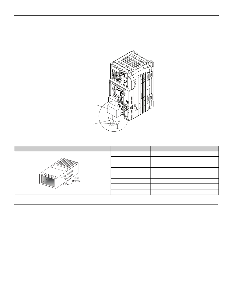
Terminal CN1
The communication connector on the option is a modular, dual port, RJ45 female communication connector designated
CN1. CN1 is the connection point for a customer supplied male Ethernet network RJ45 CAT5e (STP) communication
cable.
Figure 3
Figure 3 RJ45 Connections
Table 2 Male 8-way Ethernet Modular Connector (Customer-Supplied)
Option LED Display
The option has six LEDs:
Bi-color Status LEDs:
• Module status (MS) red/green
• Network status (NS) red/green
Ethernet LEDs (2 each):
• Network speed-10/100 yellow
• Link status and network activity-Link/Act green
The operational states of the option LEDs after the power-up diagnostic LED sequence is completed are described in
. The states with a number in parenthesis are the number of pulses of 250 ms on, 250 ms off cycles, followed by
500 ms off, then repeating the cycle. Wait at least 2 seconds for the power-up diagnostic process to complete before
verifying LED states.
Male EtherNet 8-Way Modular Connector
Pin
Description
1 (Pair 2)
Transmit data (TXD) +
2 (Pair 2)
Transmit data (TXD) -
3 (Pair 3)
Receive data (RXD) +
4 (Pair 1)
<1> Not used for 10 Mbps and 100 Mbps networks.
5 (Pair 1)
Not used
6 (Pair 3)
Receive data (RXD) -
7 (Pair 4)
Not used
8 (Pair 4)
Not used
RJ45 CAT5e
Network
Communication Cable
RJ45 CAT5e Female
Communication Cable
Ports 1 and 2