Irritrol PRO-MAX User Manual
Page 23
Pro Max User’s Manual
Rain Master Irrigation Systems
Step 3 Connect the wire for the PC Cable COMMON to the COMMON terminal of the
controller.
Step 4 Important! If 24 Volts AC is not available from the controller’s terminal strip,
see Section 3.5 and skip to Step 6 below.
Step 5 Connect the wire from the PC cables 24 Volts AC to the 24 Volts AC terminal
of the controller. Note that the PC cable has only one wire for 24 Volts AC
despite the controller having two 24 Volts AC terminals. This is because the
controller takes one of its 24 Volts AC terminals and connects it to the
COMMON terminal and you have already attached the PC cables COMMON
wire to the controller’s COMMON terminal.
You must find which 24 Volts AC terminal on the controller is NOT electrically
the same as the controller’s COMMON terminal and connect the PC’s 24 Volt
AC wire to it.
Using a voltmeter, power up the controller and set the voltmeter on a 30 Volts
or higher AC scale. Place one of the voltmeter leads ON the controller’s
COMMON terminal and use the other lead of the meter to read each of the 24
Volt AC terminals. Connect the PC cables 24 Volt AC wire to whichever
terminal gives a reading of 24 Volt AC on the meter.
If the controller does not have any terminals marked 24 Volts AC then leave
one of the voltmeter leads ON the controller’s COMMON and try the other lead
of the meter to measure the low voltage wires ON the secondary of the
controller’s transformer. Connect the PC cables 24 Volts AC wire to whichever
terminal provides a reading of 24 Volts AC ON the meter.
Step 6 Place the Rain switch in the OFF or Rain position.
Step 7 Connect the 9-pin female end of the PM-SER99 cable to the Pro Max receiver
and the male end to the universal adapter. Hands tighten the screw locks.
Step 8 Align the large connector of the RMIS Part Number 32PC cable with the
connector ON the universal adapter and plug them together.
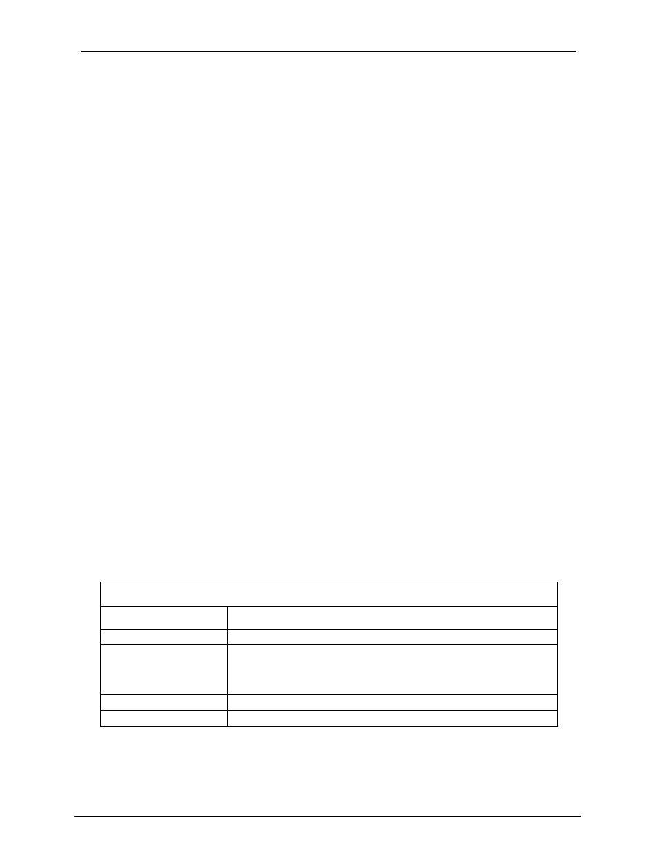
Step 9 Reconnect power to the controller. Refer to the following table:
Upon Receiver Connection
Beep Response
Description
1 Beep (1/2 sec)
Ready for use.
2 Beeps
Multi-Pro Max receiver mode:
• Requires corresponding access code to enable Pro
Max receiver operation.
3 Beeps
Failed internal diagnostic tests. Contact Rain Master.
No Beeps
Check the 24 Volts AC and COMMON connections.
Page 18