Whelen 71163 User Manual
Aviation, Engineering company inc
Page 1
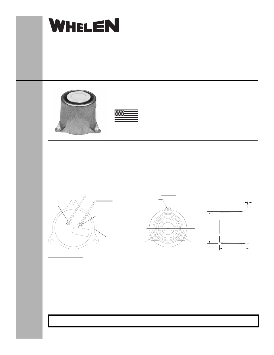
2.56 ± .06
DIA. AT BASE
2.28 ± .06
.09
®
ENGINEERING COMPANY INC.
Route 145, Winthrop Road,
Chester, Connecticut 06412
Phone: (860) 526-9504
Fax: (860) 526-2009
Internet: www.whelen.com
Sales/Service e-mail: [email protected]
Aviation
Installation Guide:
Ground Crew Call Horn
P/N 01-0771163-00
©2007 Whelen Engineering Company Inc.
Form No.14113A (082813)
MADE IN THE U.S.A.
INSTALLATION PROCEDURES: The following information is
to assist in the installation of a Whelen Ground Crew Call Horn.
1.
Using approved connectors, wire the unit as shown (Fig.1).
Tighten the hardware until a maximum torque value of 6
in./lbs. is achieved.
2.
Install the unit using the mounting diagram shown (Fig.2).
Insure that the wire leads are clear of any obstructions and
ty-wrap as required.
3.
Check all avionics systems for interference from the
installation.
4.
A flight check should be performed by a properly certified
pilot.
5.
Update aircraft records, complete Form 337 and obtain
FAA field approval for installation, if necessary.
.180 DIA. (3) HOLES
EQUALLY SPACED ON A
3.125 ± .010 DIA.
TOP VIEW
CL
CL
GENERAL NOTES
• VOLTAGE - 28V NOM. (18VDC MIN TO 32VDC MAX.)
• CURRENT @ 28V - 55ma TYP. / 600ma MAX
• SOUND INTENSITY - The signal provides a sound intensity of 105dB (+13dB - 3dB) as indicated on a standard meter at a distance
of 3 feet when operated at 28VDC under conditions encountered in a sound-proof room.
• FREQUENCY - 25-20,000 HZ
• WEIGHT - 0.65 lbs. (MAX)
+28V
GROUND, NEG. (-)
Terminal Posts
#6-32NC-3A
#6-32 Self-Locking Nut
MS21043-06
(2) Incl.
Crew Call Horn
POS. (+) 28VDC
Fig.1
Fig.2
For warranty information regarding this product, visit www.whelen.com/warranty