Whelen 9061500 User Manual
Aviation
Page 1
®
ENGINEERING COMPANY INC.
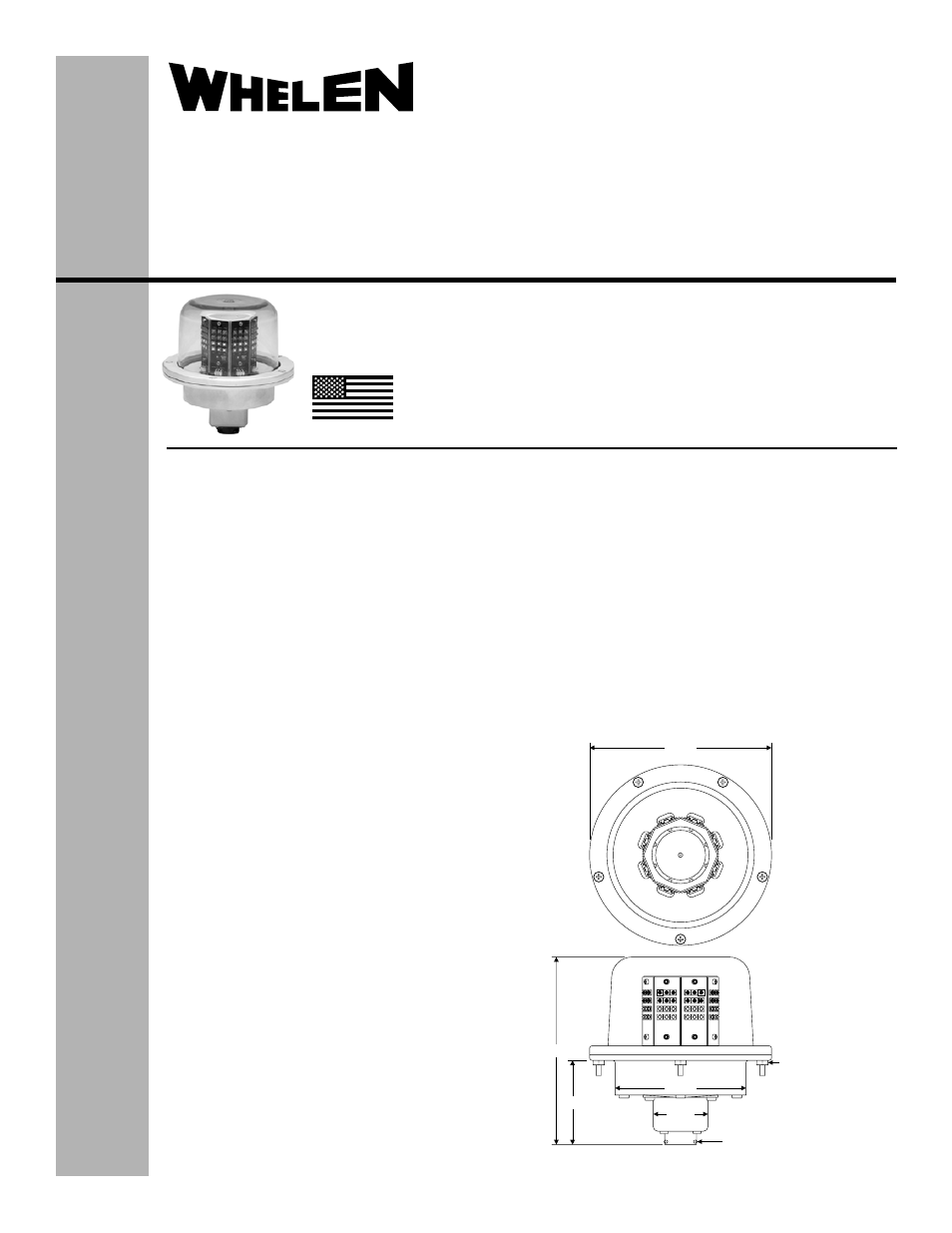
5.20
2.33
Ø3.60
1.50
MS3112E14-5P
CONNECTOR
#6-32 nuts for shipping
purposes only. Remove
prior to installation on
aircraft.
Ø5.00
51 Winthrop Road
Chester, Connecticut 06412-0684
Phone: (860) 526-9504
Fax: (860) 526-2009
Internet: www.whelen.com
Sales/Service e-mail: [email protected]
Aviation
Installation Guide:
Model 90615( )-series
Model(s) 9061500, 9061510
P/N:01-0790615-00, 01-0790615-10
LED Dual Color Anti-Collision
Light Assembly
©2010 Whelen Engineering Company Inc.
Form No.14428 (102010)
SPECIFICATIONS:
Nominal Operational Voltage:.......................28 VDC
(Operation from 22-32 VDC)
LED Anti-Collision Light (Average): ................. 0.9 Amps
LED Anti-Collision Light ([email protected] sec.): ... 4.9 Amps
Flashrate.......................................................... 45± 5 per min.
Model 90615 is a combination White, Class II, and Red, Class
III LED Anti-Collision Light.
EQUIPMENT LIMITATIONS:
The baseplate must be mounted parallel to the vertical and
horizontal centerlines of the aircraft to project the patterns
properly.
An upper and lower unit is required to comply with the TSO-
C96a requirements for a Class II Anti-Collision light system
below the horizontal plane.
The white LED anti-collision light and red LED anti-collision
light are not designed to be on at the same time.
Certain types of installations may require additional testing.
CONTINUED AIRWORTHINESS:
The anti-collision light is designed with 8 vertical columns.
Each column consists of 6 white and 6 red LEDs. Should any
one LED fail the unit must be repaired or replaced. Inspect
the lens. Replace if there is excessive scratching, pitting,
discoloration or cracking.
Note: The unit has an internal diagnostic circuit to detect
failures. The anti-collision light will automatically shut off after
9-10 flashes if a failure is detected.
INSTALLATION PROCEDURES:
The following information is to assist in the installation of a
Whelen Anti-collision light system.
1.
The installation procedure described in the following text
will be confined to a single light installation, but is
identical for multiple light installations.
2.
Connect the anti-collision inputs according to the chart
shown. Connect the power leads to an appropriately
TSO-C96a
CLASS II (White)
Class III (Red)
APPROVED
MADE IN THE U.S.A.
The conditions and tests required for TSO approval of this
article are minimum performance standards. It is the
responsibility of those installing this article either on or
within a specific type or class of aircraft to determine that
the aircraft installation conditions are within the TSO
standards. TSO articles must have separate approval for
installation in aircraft. The article may be installed only if
performed under 14 CFR part 43 or the applicable
airworthiness requirements.
sized breaker. Connections to be in accordance with
FAA approved methods.
3.
Using appropriate hardware, install the light assembly
and insure that all leads are clear of any obstructions
and secured as required. Secure light assembly using
vibration resistant threaded fasteners.
4.
Check all avionics systems for interference from this
installation.
5.
A flight check should be performed by a properly certified
pilot.
6.
When necessary, waterproof the light base to the
aircraft. Apply single part silicone (RTV) or equivalent
around any open area where water could get in.
7.
Update aircraft records, complete Form 337 and obtain
FAA field approval for installation, as required.