Earth 3 wires – Amprobe GP-2 Geo-Test User Manual
Page 12
GP-2 GeoTest
EN - 12
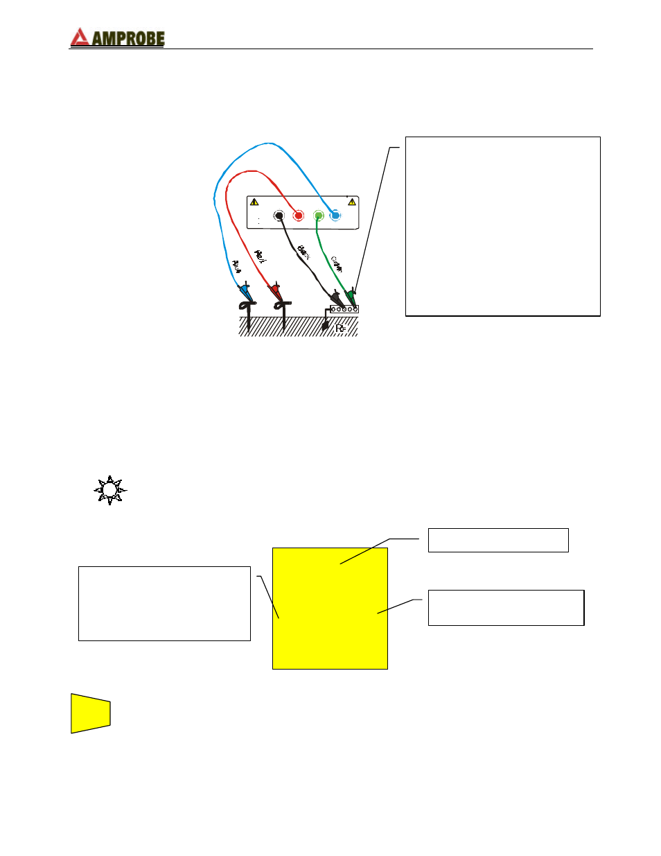
4.2. EARTH 3 WIRES
The measurement is taken according to what is prescribed for CEI 64.8, IEC 781, VDE
0413, EN61557-5 standards.
ES
H
E
CAT III
440 V P-N-PE
2 5 0 V
S
H
ES
E
S
H
Figure 3: 3 wires earth resistance measurement
Measuring procedure:
F
Insert the 4 connectors (black, red, blue and green) of the cables into the
corresponding input terminals of the instrument (E, S, H, ES).
F
Connect the alligator clips as shown in Figure 3.
F
Position the switch to EARTH 3 WIRES.
Display appearance:
---
---
0
0
V
- - -
- - -
Press GO to take the measurement and read the value on the display. At the
end of the test, a screen similar to the one below will be displayed.
NOTE!
If you keep pressing GO, the instrument takes more measurements
consecutively. When a new value is displayed, the symbol
Ω
blinks on the main
display, the instrument emits a short sound and the counter shown on the
Main display
Secondary display on the left-
hand side:
In this mode it displays the
eventual interfering voltage
present on the circuit
Secondary display on the
right-hand side
GO
Small earth plant:
- current probe (terminal H, blue
wire) positioned a distance from
the earth equipment outline
corresponding to five times the
diagonal of the area of the earth
equipment.
Large earth plant:
- current probe (terminal H, blue
wire) positioned a distance from
the earth equipment outline
corresponding the diagonal of
the area of the earth equipment.