Amprobe GP-2 Geo-Test User Manual
Page 13
GP-2 GeoTest
EN - 13
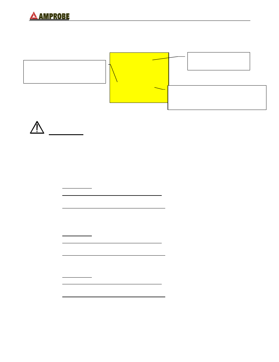
secondary display on the left-hand side is updated. This counter indicates the
quantity of measurements included in the calculation of the average resistance
value.
0.96
0.96
Ω
Ω
2
2 0.93
0.93
Ω
Ω
WARNING:
When the message “Measuring” appears on the display, the
instrument is measuring. Do not disconnect the alligator
clips during the measurement
.
Ex.:
if the operator takes three measurements consecutively, the instrument will
display:
- 1
st
measurement:
main display = measured resistance value (Ex: 0.90
Ω
)
secondary display on the left-hand side = 001 (no. of measurements = 1
means that 1 earth measurement has been taken)
secondary display on the right-hand side = average of the measurements
taken (in case just one measurement has been taken the average value is
equal to the measured value, in this case 0.90
Ω
)
- 2
nd
measurement:
main display = measured resistance value (Ex: 0.96
Ω
)
secondary display on the left-hand side = 002 (no. of measurements = 2
means that 2 earth measurements have been taken consecutively)
secondary display on the right-hand side = average of the measurements
taken ((Val1+Val2)/no. of measurements = (0.90+0.96)/2 = 0.93
Ω
)
- 3
rd
measurement:
main display = measured resistance value (Ex: 0.93
Ω
)
secondary display on the left-hand side = 003 (no. of measurements = 3
means that 3 earth measurements have been taken consecutively)
secondary display on the right-hand side = average of the measurements
taken ((Val1+Val2)/no. of measurements = (0.90+0.96+0.93)/3 = 0.93
Ω
)
No. of earth resistance
measurements included in the
calculation of the average resistance
Average value of the resistance calculated
as:
(Val1+Val2+…+Valn)/(no. measurements)
Value of the resistance
measured