Amprobe GP-2 Geo-Test User Manual
Page 39
GP-2 GeoTest
EN - 39
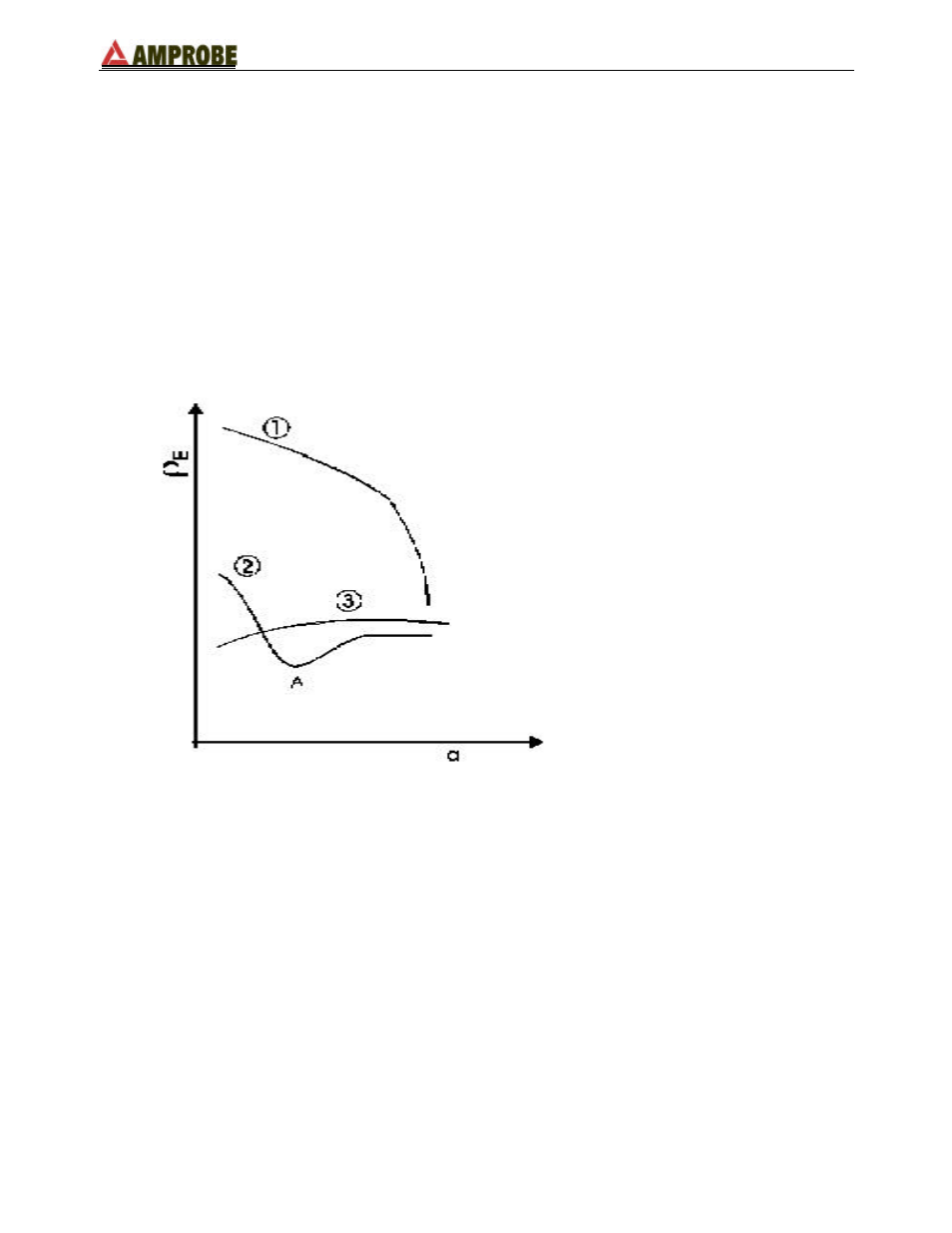
The measuring method allows definition of the specific resistance up to the depth
approximately corresponding to the distance “a” between the rods. If you increase the
distance “a” you can reach deeper ground layers and check the ground homogeneity. After
several
ρ
measurements, at growing distances “a”, you can trace a profile like the following
ones, according to the most suitable rod chosen:
Curve1: as
ρ
decreases only in depth, it is possible to use only a rod in depth.
Curve2: as
ρ
decreases only until the depth A, it is not useful to increase the depth of the
rod beyond A.
Curve3: even at a superior depth,
ρ
does not decrease, therefore a ring rod must be used.
APPROXIMATE EVALUATION OF THE CONTRIBUTION OF INTENTIONAL RODS (64-
12 2.4.1)
The resistance of a rod Rd can be calculated with the following formulas (
ρ
= average
resistivity of the ground).
a) resistance of a vertical rod
Rd =
ρ
/ L
L= length of the element touching the ground
b) resistance of an horizontal rod
Rd = 2
ρ
/ L
L= length of the element touching the ground
c) resistance of linked elements
The resistance of a complex system with more elements in parallel is always higher
than the resistance which could result from a simple calculation of elements in
(ft / m)
(
Ω
m)