Amprobe GP-2 Geo-Test User Manual
Page 9
GP-2 GeoTest
EN - 9
4. SWITCH FUNCTIONS
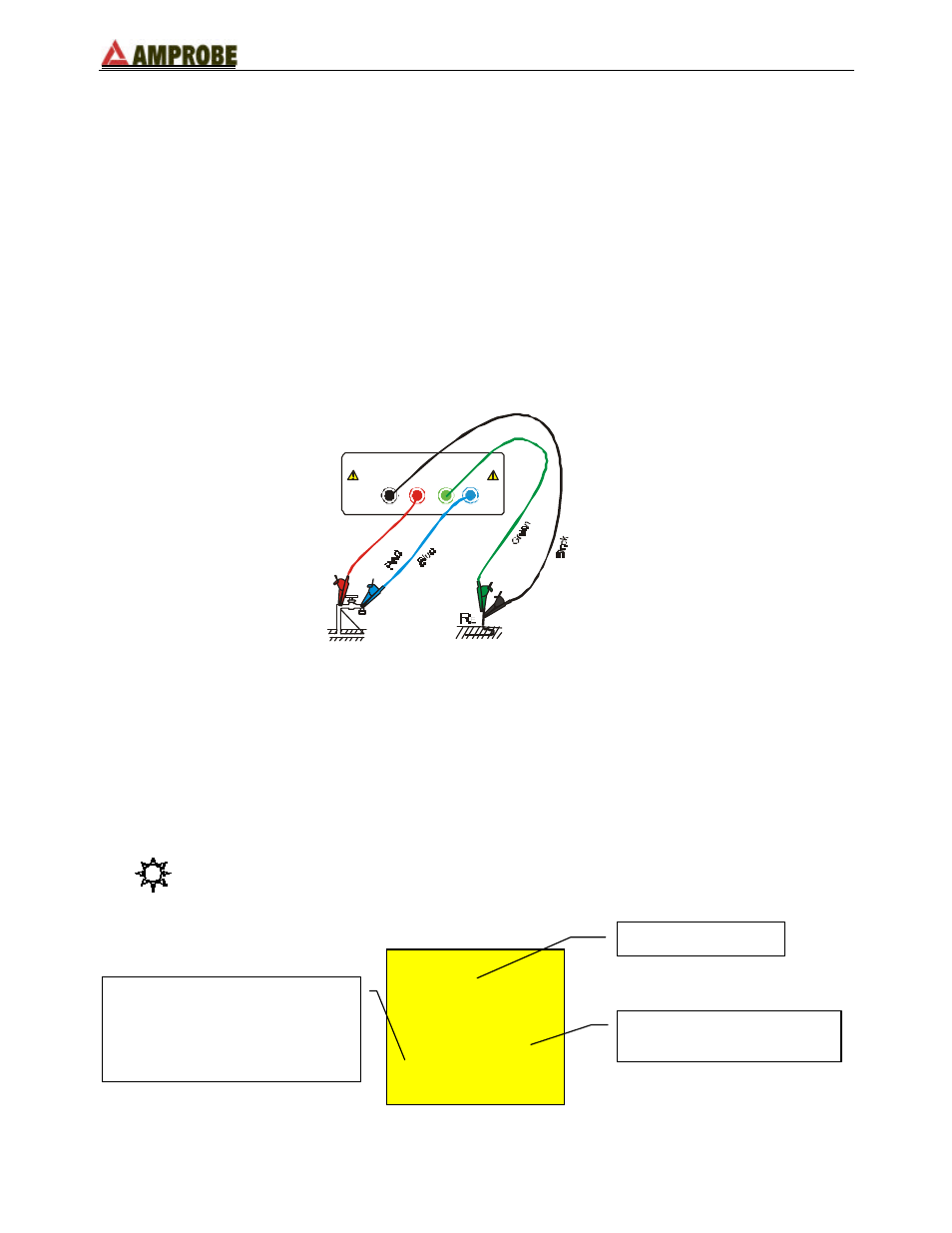
4.1. EARTH 2 WIRES
Whenever it is not possible to drive rods into the ground to take a 3-wire measurement, or
in case of TT installations it is possible to use the simplified 2-wire method (Figure 2)
which gives an excess (therefore safer) value.
To carry out the test a suitable auxiliary rod is necessary; a rod is “suitable” when its earth
resistance is negligible and it is independent of the earth equipment under test.
In Figure 2 a water pipe has been used as auxiliary rod. However, any metal body driven
into the ground can be used, provided that the above said requirements are met.
Although this test is not provided for by the CEI 64.8 standard at present, it gives a value,
which many 3-wire comparison tests have proved to be revealing for earth resistance.
ES
E
S
H
Figure 2: 2 wire earth resistance measurement
Measuring procedure:
F
Insert the 4 connectors (black, red, blue and green) of the measuring cables into the
corresponding input terminals of the instrument (E, S, H, ES).
F
Connect the alligator clips as shown in Figure 2.
F
Position the switch on EARTH 2 WIRES.
Display appearance:
---
---
0
0
V
- - -
- - -
Main display
Secondary display on the left-
hand side:
In this stage it displays the
eventual interfering voltage
present on the circuit
Secondary display on the
right-hand side