Earth resistivity measurement – Amprobe GP-2 Geo-Test User Manual
Page 38
GP-2 GeoTest
EN - 38
11.2. EARTH RESISTIVITY MEASUREMENT
PURPOSE OF THE TEST
This test is intended to analyze the resistivity value of the ground in order to define the
type of rods to be used.
EQUIPMENT PARTS TO BE TESTED
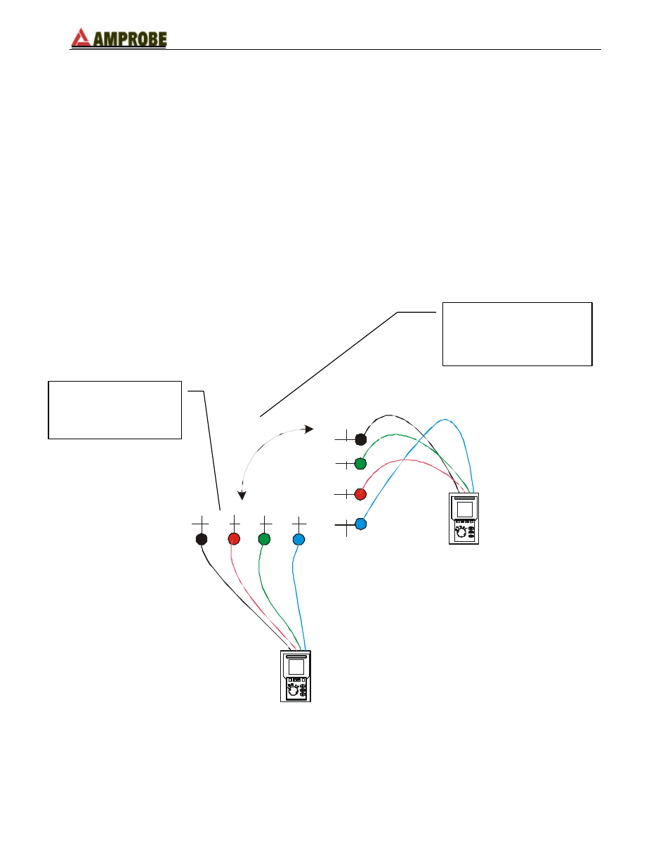
For the resistivity test admissible values do not exist. The various values measured by
positioning the rods at growing distances “a” must be quoted in a graph. According to the
resulting curve, suitable rods will be chosen. As the test result can be affected by metal
parts buried (such as pipes, cables or other rods), in case of doubt take a second
measurement positioning the rods at an equal distance "a", but rotating their axis by 90°.
Black
B
la
ck
Blue
B
lu
e
Green
G
re
e
n
Red
R
e
d
a
a
a
a
a
a
90°
The resistivity value is calculated with the following formula:
ρ
=2
π
aR
where:
ρ
= specific resistivity of the ground (
Ω
m)
a= distance between the rods (ft/m)
R= resistance measured by the instrument (
Ω
)
2nd measurement:
compared to the previous
measurement the rods are
rotated by 90°.
1st measurement:
the rods are positioned
at a distance “a”