ProSoft Technology MVI69-EGD User Manual
Page 80
MVI69-EGD ♦ CompactLogix or MicroLogix Platform
Reference
GE Ethernet Global Data Communication Module
Page 80 of 96
ProSoft Technology, Inc.
November 3, 2008
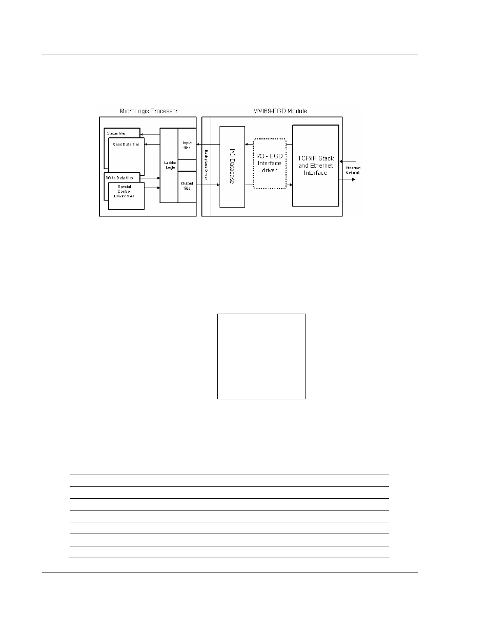
The following illustration shows the data transfer method used to move data
between the CompactLogix or MicroLogix processor and the MVI69-EGD
module.
All data transferred between the module and the processor over the backplane is
through the input and output images. Ladder logic must be written in the
CompactLogix or MicroLogix processor to interface the input and output image
data with data defined in the Controller Tags. All data used by the module is
stored in its internal database. The following illustration shows the layout of the
database:
Module's Internal Database Structure
4000 registers for user data
0
Register Data
3999
Data contained in this database is paged through the input and output images by
coordination of the CompactLogix or MicroLogix ladder logic and the MVI69-EGD
module's program. Up to 248 words of data can be transferred from the module
to the processor at a time. Up to 247 words of data can be transferred from the
processor to the module. The read and write block identification codes in each
data block determine the function to be performed or the content of the data
block. The module uses the following block numbers:
Block Range
Descriptions
-1 or 0
Empty Data Blocks
1 to 67
Data Read or Write Blocks
2000
CP Status Data
9250
General Status Data
9998
Warm-boot control block
9999
Cold-boot control block