Using a heat sink, Θja bottom θjc θsa – Altera PowerPlay Early Power Estimator User Manual
Page 21
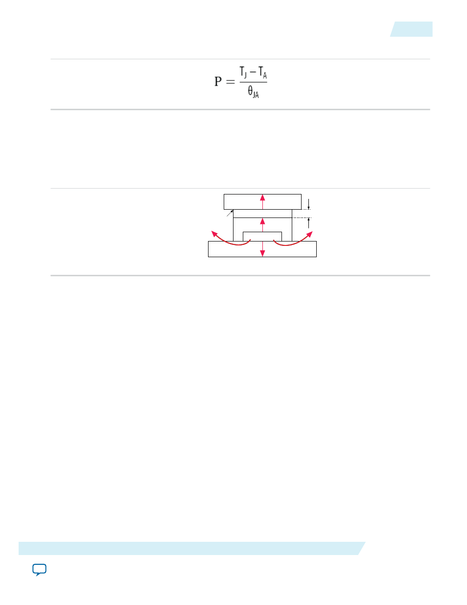
Figure 3-8: Total Power
Using a Heat Sink
When you use a heat sink, the major paths of power dissipation are from the device through the case,
thermal interface material, and heat sink. There is also a path of power dissipation through the board. The
path through the board has less impact than the path to air.
Figure 3-9: Thermal Representation with a Heat Sink
Heat Sink
Case
Device
Board
Thermal interface material
θJA BOTTOM
θJC
θSA
Thermal Representation with Heat Sink
θCS
In the model used in the PowerPlay EPE spreadsheet, power is dissipated through the board or through
the case and heat sink. The junction-to-board thermal resistance (θ
JA BOTTOM
) refers to the thermal
resistance of the path through the board. Junction-to-ambient thermal resistance (θ
JA TOP
) refers to the
thermal resistance of the path through the case, thermal interface material, and heat sink.
UG-01070
2015.01.20
Using a Heat Sink
3-11
PowerPlay Early Power Estimator Worksheets
Altera Corporation