Ram worksheet, Ram worksheet -16 – Altera PowerPlay Early Power Estimator User Manual
Page 26
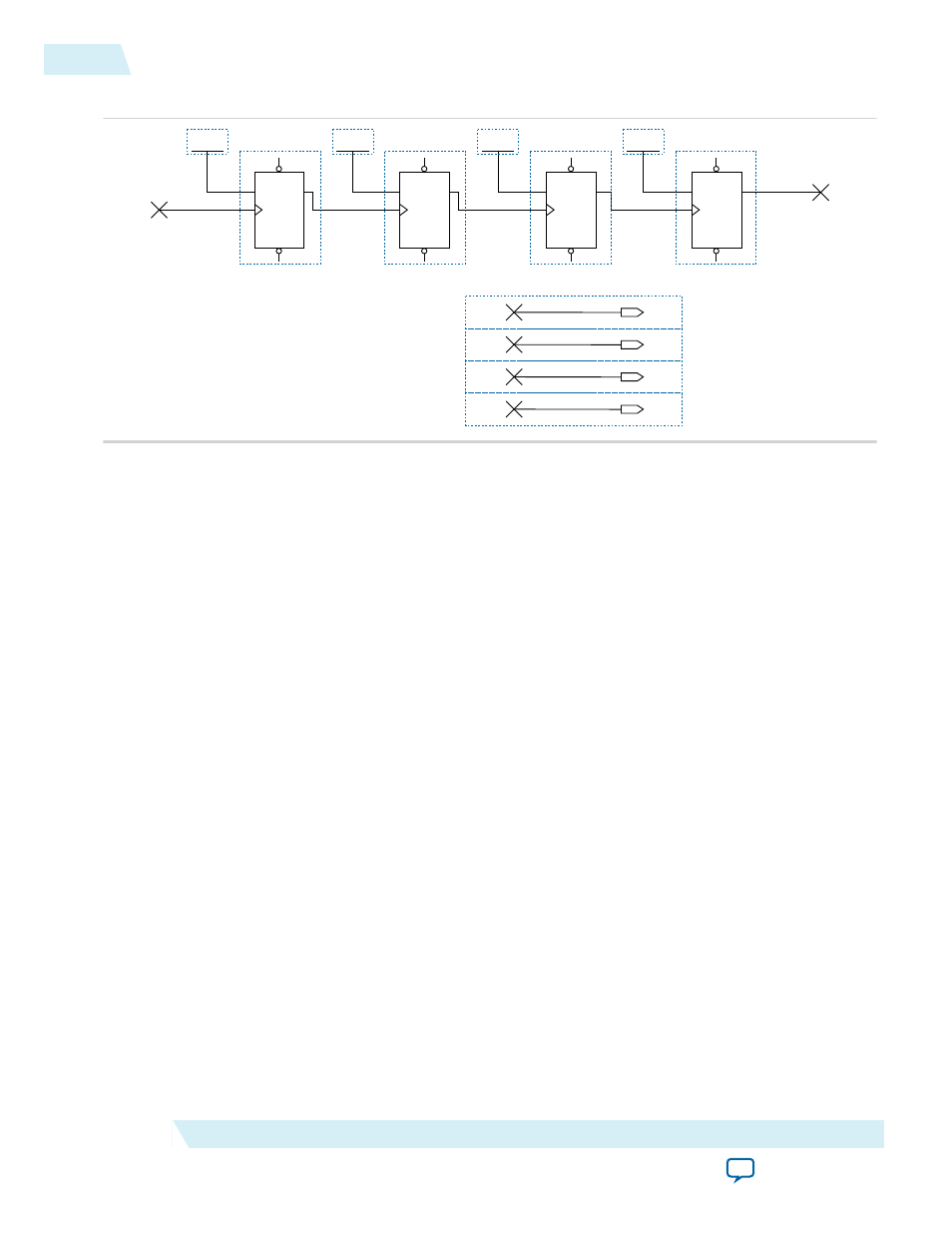
Figure 3-14: 4-Bit Counter Example
TFF
PFN
T
Q
CLRN
TFF
PFN
T
Q
CLRN
TFF
PFN
T
Q
CLRN
TFF
PFN
T
Q
CLRN
VCC
VCC
VCC
VCC
cout2
cout1
cout0
clock
cout3
OUTPUT
cout0
cout0
OUTPUT
cout3
cout3
OUTPUT
cout2
cout2
OUTPUT
cout1
cout1
The first TFF with the
cout0
LSB output has a toggle rate of 100% because the signal toggles on every
clock cycle. The toggle rate for the second TFF with
cout1
output is 50% because the signal only toggles
on every two clock cycles. Consequently, the toggle rate for the third TFF with
cout2
output and fourth
TFF with
cout3
output are 25% and 12.5%, respectively. Therefore, the average toggle percentage for
this 4-bit counter is (100 + 50 + 25 + 12.5)/4 = 46.875%.
For more information about logic block configurations of the supported device families, refer to the
“Logic Array Blocks and Adaptive Logic Modules” chapter of the respective device handbook.
RAM Worksheet
Each row in the RAM worksheet of the PowerPlay EPE spreadsheet represents a design module where the
RAM blocks are the same type, have the same data width, the same RAM depth (if applicable), the same
RAM mode, and the same port parameters. If some or all of the RAM blocks in your design have different
configurations, enter the information in different rows. For each design module, enter the type of RAM
implemented, the number of RAM blocks, and the RAM block mode.
Each row in the RAM worksheet of the PowerPlay EPE spreadsheet can also represent a logical RAM
module that can be physically implemented on more than one RAM block. The PowerPlay EPE
spreadsheet implements each logical RAM module with the minimum number of physical RAM blocks,
in the most power-efficient way possible, based on the width and depth of the logical instance entered.
You must know how your RAM is implemented by the Quartus II Compiler when you are selecting the
RAM block mode. For example, if a ROM is implemented with two ports, it is considered a true dual-port
memory and not a ROM. Single-port and ROM implementations only use Port A. Simple dual-port and
true dual-port implementations use Port A and Port B.
3-16
RAM Worksheet
UG-01070
2015.01.20
Altera Corporation
PowerPlay Early Power Estimator Worksheets