I/o worksheet, I/o worksheet -22 – Altera PowerPlay Early Power Estimator User Manual
Page 32
I/O Worksheet
Each row in the I/O section represents a design module where the I/O pins have the same I/O standard,
input termination, current strength or output termination, data rate, clock frequency, output enable static
probability, and capacitive load. Enter the following parameters for each design module:
• I/O standard
• Input termination
• Current strength/Output termination
• Slew rate
• Differential output voltage (V
OD
) setting
• Pre-emphasis setting
• Number of input, output, and bidirectional pins
• I/O data rate
• Clock frequency (f
MAX
) (in MHz)
• Average pin toggle percentage
• Output enable static probability
• Capacitance of the load
For the EPE spreadsheet version 11.0 onwards, Off Chip Power (W) information is added into the I/O
worksheet.
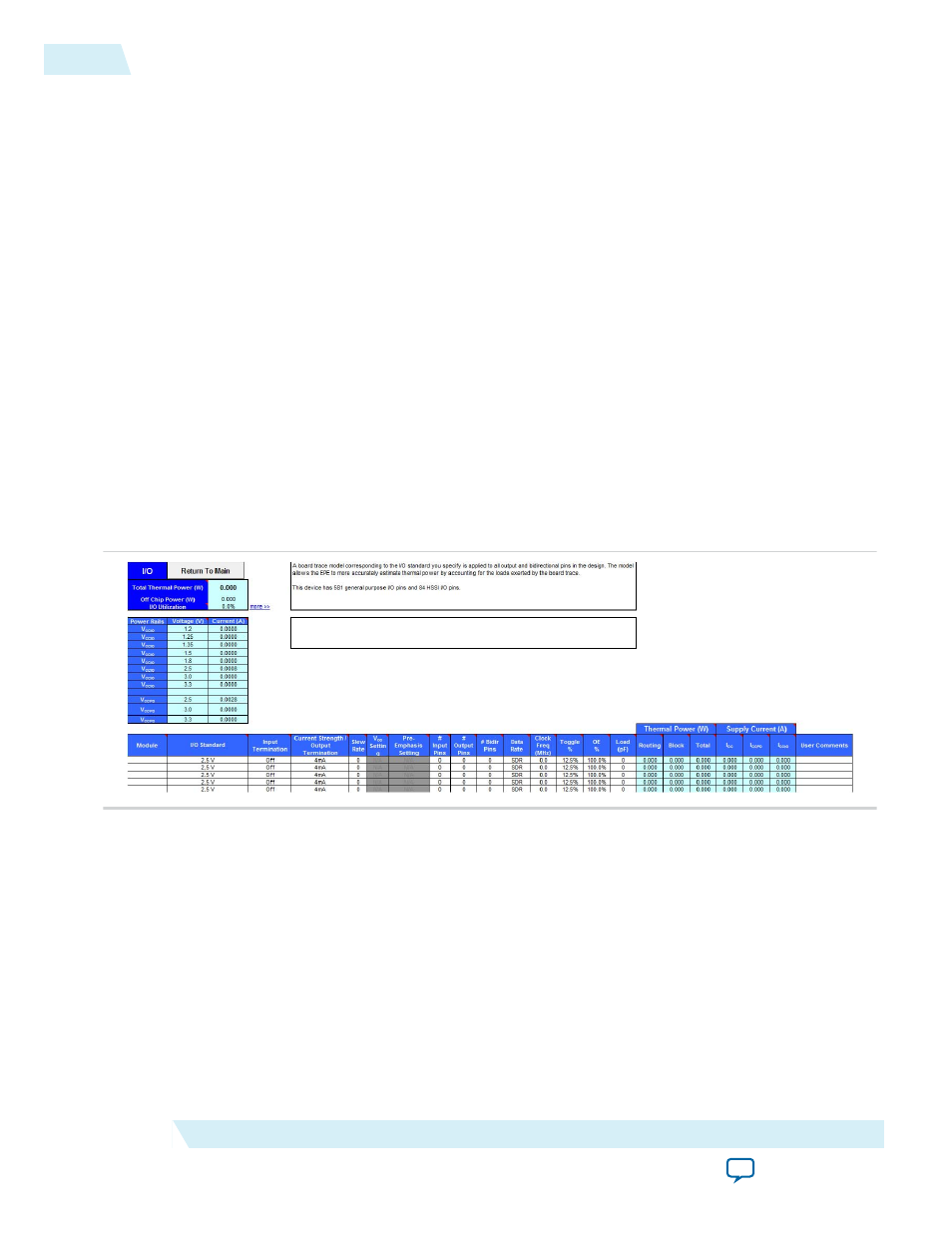
Figure 3-17: I/O Worksheet of the PowerPlay EPE Spreadsheet
When using the PowerPlay EPE spreadsheet, it is assumed you are using external termination resistors
when you design with I/O standards that recommend termination resistors (SSTL and high-speed
transceiver logic [HSTL]). If your design does not use external termination resistors, choose the LVTTL/
LVCMOS I/O standard with the same VCCIO and similar current strength as the terminated I/O
standard. For example, if you are using the SSTL-2 Class II I/O standard with a 16 mA current strength,
you must select 2.5 V as the I/O standard and 16 mA as the current strength in the PowerPlay EPE
spreadsheet.
To use on-chip termination (OCT), select the Current Strength/Output option in the EPE spreadsheet.
The power reported for the I/O signals includes thermal and external I/O power. The total thermal power
is the sum of the thermal power consumed by the device from each power rail, as shown in the following
equation.
3-22
I/O Worksheet
UG-01070
2015.01.20
Altera Corporation
PowerPlay Early Power Estimator Worksheets