Altera PowerPlay Early Power Estimator User Manual
Page 35
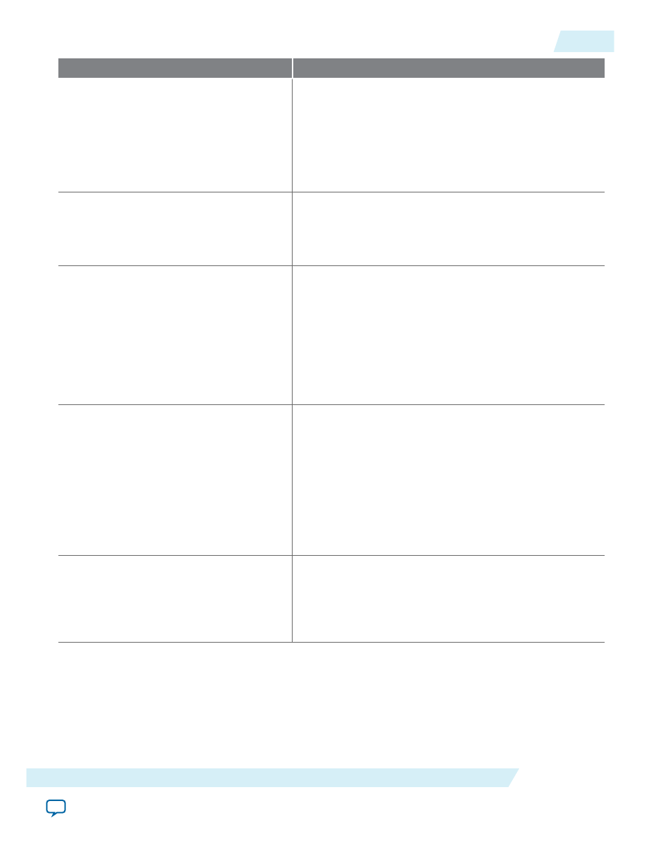
Column Heading
Description
Data Rate
Select either SDR or DDR as the I/O data rate.
This indicates whether the I/O value is updated once (single
data rate [SDR]) or twice (double data rate [DDR]) in a
clock cycle. If the data rate of the pin is DDR, it is possible
to set the data rate to SDR and double the toggle percentage.
The Quartus II software uses this method to output
information.
Clock Freq (MHz)
Enter the clock frequency (in MHz). This value is limited by
the maximum frequency specification for the device family.
100 MHz with a 12.5% toggle means that each I/O pin
toggles 12.5 million times per second (100 × 12.5%).
Toggle %
Enter the average percentage of input, output, and bidirec‐
tional pins toggling on each clock cycle. For input pins used
as clocks, the toggle percentage ranges from 0 to 200%
because clocks toggle at twice the frequency.
If the pins use DDR circuitry, you can set the data rate to
SDR and double the toggle percentage. The Quartus II
software uses this method to output information. Typically,
the toggle percentage is 12.5%. To be more conservative,
you can use a higher toggle percentage.
OE %
Enter the average percentage of time that the:
• Output I/O pins are enabled.
• Bidirectional I/O pins are outputs and enabled.
During the remaining time the:
• Output I/O pins are tristated.
• Bidirectional I/O pins are inputs.
The value you enter must be a percentage between 0 and
100%.
Load (pF)
Enter the pin loading external to the chip (in pF).
This only applies to outputs and bidirectional pins. Pin and
package capacitance is already included in the I/O model.
Therefore, only include the off-chip capacitance in the Load
parameter.
UG-01070
2015.01.20
I/O Worksheet
3-25
PowerPlay Early Power Estimator Worksheets
Altera Corporation