Θja bottom θjc θcs θsa, Θja top = θjc+ θcs + θsa – Altera PowerPlay Early Power Estimator User Manual
Page 22
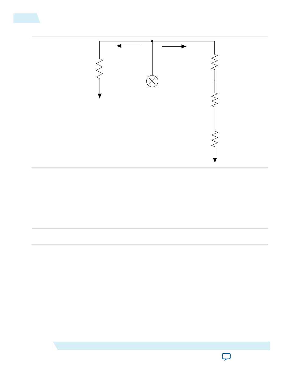
Figure 3-10: Thermal Model for the PowerPlay EPE Spreadsheet with a Heat Sink
TJ
TA
Power (P1)
Heat Source
Power (P2)
TJ
TC
TS
TA
θJA BOTTOM
θJC
θCS
θSA
If you want the PowerPlay EPE spreadsheet thermal model to take the θ
JA BOTTOM
into consideration, set
the Board Thermal Model parameter to either JEDEC (2s2p) or Typical Board. Otherwise, set the Board
Thermal Model parameter to None (conservative). In this case, the path through the board is not
considered for power dissipation and a more conservative thermal power estimate is obtained.
The addition of the junction-to-case thermal resistance (θ
JC
), the case-to-heat sink thermal resistance
(θ
CS
) and the heat sink-to-ambient thermal resistance (θ
SA
) determines the θ
JA TOP
.
Figure 3-11: Junction-to-Ambient Thermal Resistance
θJA TOP = θJC+ θCS + θSA
Based on the device, package, airflow, and heat sink solution selected in the Input Parameters section, the
PowerPlay EPE spreadsheet determines the θ
JA TOP
.
If you use a low, medium, or high profile heat sink, select the airflow from the values of Still Air and air
flow rates of 100 lfm (0.5 m/s), 200 lfm (1.0 m/s), and 400 lfm (2.0 m/s). If you use a custom heat sink,
enter the custom θ
SA
value. You must incorporate the airflow into the custom θ
SA
value. Therefore, the
Airflow parameter is not applicable in this case. You can obtain these values from the heat sink manufac‐
turer.
The ambient temperature does not change, but the junction temperature changes depending on the
thermal properties. Because a change in junction temperature affects the thermal device properties that
are used to calculate junction temperature, calculating the junction temperature is an iterative process.
3-12
Using a Heat Sink
UG-01070
2015.01.20
Altera Corporation
PowerPlay Early Power Estimator Worksheets