Max ii cpld epm2210 system controller, Max ii cpld epm2210 system controller –7 – Altera Arria II GX FPGA Development Board User Manual
Page 15
Chapter 2: Board Components
2–7
MAX II CPLD EPM2210 System Controller
February 2011
Altera Corporation
Arria II GX FPGA Development Board Reference Manual
The specific I/O resources available in the Arria II GX EP2AGX260EF35 device are
listed in
“General User Input/Output” on page 2–24
. A second HSMC port is
available in the Arria II GX EP2AGX260EF35 device to support an extra transceiver
quadrant and additional I/O banks.
MAX II CPLD EPM2210 System Controller
The board utilizes the EPM2210 System Controller, an Altera MAX
II CPLD, for the
following purposes:
■
FPGA configuration from flash memory
■
Power consumption monitoring
■
Virtual JTAG interface for PC-based GUI
■
Control registers for clocks
■
Control registers for remote system update
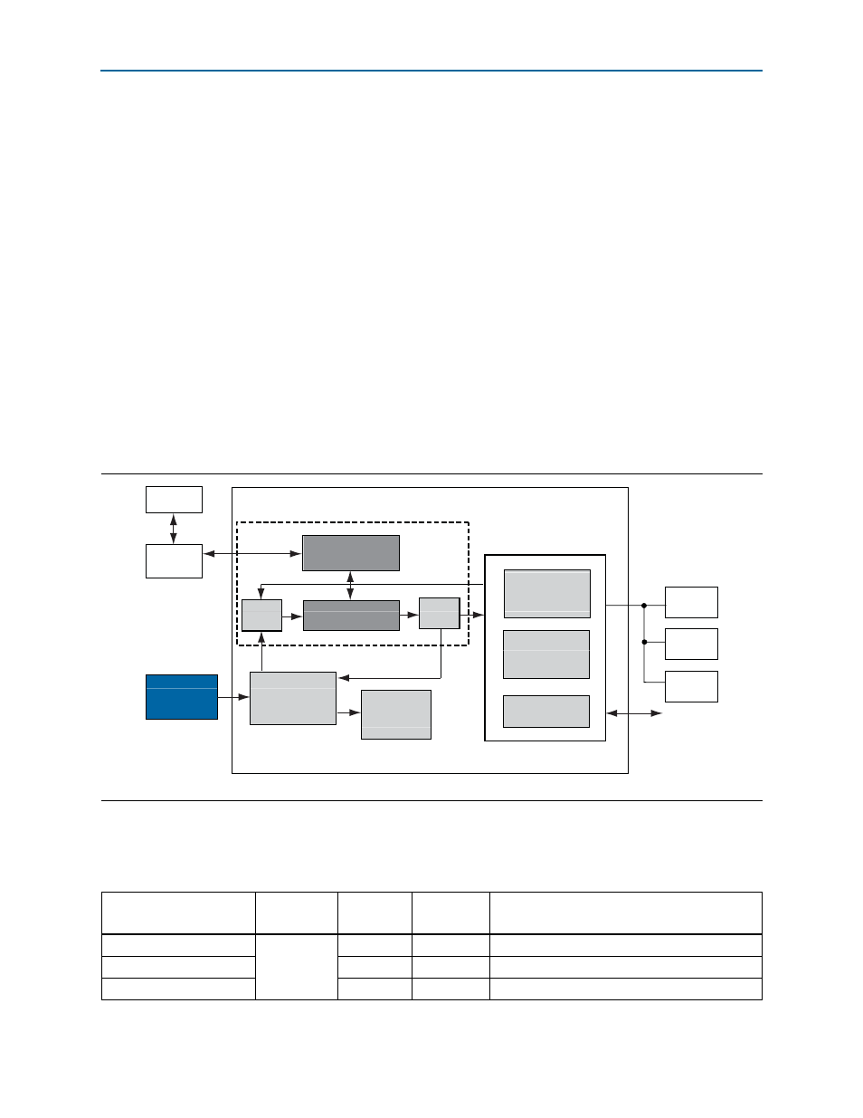
illustrates the MAX II CPLD EPM2210 System Controller's functionality
and external circuit connections as a block diagram.
Table 2–7
lists the I/O signals present on the MAX
II CPLD EPM2210 System
Controller. The signal names and functions are relative to the MAX
II device (U32).
Figure 2–3. MAX II CPLD EPM2210 System Controller Block Diagram
Information
Register
Embedded
Blaster
MAX II CPLD EPM2210 System Controller
Power
Calculations
SLD-HUB
PFL
Power
Measurement
Results
Virtual-JTAG
PC
A2GX
LTC2418
Controller
FLASH
Decoder
Encoder
GPIO
JTAG Control
SSRAM
Control
Register
Table 2–7. MAX II CPLD EPM2210 System Controller Device Pin-Out (Part 1 of 5)
Schematic Signal Name
I/O Standard
EPM2210
Pin Number
EP2AGX125
Pin Number
Description
clk_enable
2.5-V
K14
—
DIP - clock oscillator enable
clk_sel
P2
—
DIP - clock select SMA or oscillator
clk1_ce
N3
—
Programmable oscillator 1 chip select