Altera Arria II GX FPGA Development Board User Manual
Page 19
Chapter 2: Board Components
2–11
MAX II CPLD EPM2210 System Controller
February 2011
Altera Corporation
Arria II GX FPGA Development Board Reference Manual
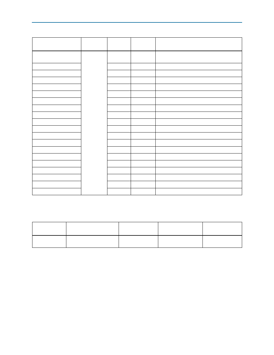
lists the MAX
II CPLD EPM2210 System Controller component reference
and manufacturing information.
reset_confign
(LOAD IMAGE)
2.5-V
A9
—
Load the flash memory identified by the
configuration LEDs
max_dip[0]
L16
—
DIP - reserved
max_dip[1]
L15
—
DIP - reserved
max_dip[2]
L14
—
DIP - reserved
max_error
B10
—
FPGA configuration error LED
max_led
B11
—
LED - reserved
max_load
A11
—
FPGA configuration active LED
max_resetn
M9
—
MAX II reset push-button
max2_ben[0]
M11
C15
FSM bus Max2 byte enable 0
max2_ben[1]
M10
H16
FSM bus Max2 byte enable 1
max2_ben[2]
N12
D14
FSM bus Max2 byte enable 2
max2_ben[3]
P12
A9
FSM bus Max2 byte enable 3
max2_clk
N10
J14
FSM bus Max2 clock
max2_csn
M12
A16
FSM bus Max2 chip select
max2_oen
M8
A14
FSM bus Max2 output enable
max2_wen
N11
B16
FSM bus Max2 write enable
sram_mode
J3
—
FSM bus SSRAM burst sequence selection
sram_zz
B3
B27
FSM bus SSRAM power sleep mode
usb_disablen
K2
—
DIP - embedded USB-Blaster disable
usb_led
K1
—
Embedded USB-Blaster active
Table 2–7. MAX II CPLD EPM2210 System Controller Device Pin-Out (Part 5 of 5)
Schematic Signal Name
I/O Standard
EPM2210
Pin Number
EP2AGX125
Pin Number
Description
Table 2–8. MAX II CPLD EPM2210 System Controller Component Reference and Manufacturing Information
Board Reference
Description
Manufacturer
Manufacturing
Part Number
Manufacturer
Website
U32
IC - MAX II CPLD EPM2210
256FBGA -3 LF 2.5V VCCINT
Altera
Corporation
EPM2210F256C3N