Setup elements, Board settings dip switch, Setup elements –18 – Altera Arria II GX FPGA Development Board User Manual
Page 26: Board settings dip switch –18
2–18
Chapter 2: Board Components
Configuration, Status, and Setup Elements
Arria II GX FPGA Development Board Reference Manual
February 2011
Altera Corporation
lists the board-specific LEDs component references and manufacturing
information.
Setup Elements
The development board includes several different kinds of setup elements. This
section describes the following setup elements:
■
Board settings DIP switch
■
JTAG chain header switch
■
PCI Express control DIP switch
■
Reset configuration push-button switches
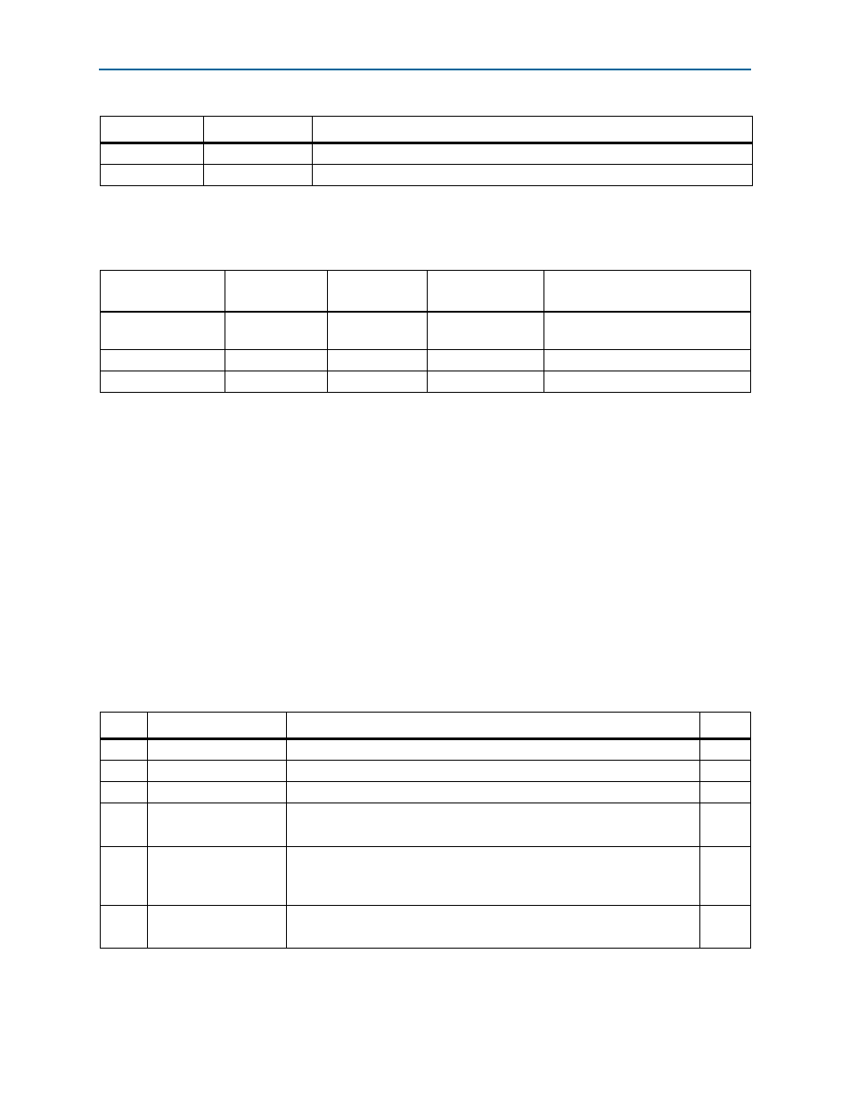
Board Settings DIP Switch
The board settings DIP switch (SW4) controls various features specific to the board
and the MAX
II CPLD EPM2210 System Controller logic design.
Table 2–13
shows the
switch controls and descriptions.
D25
PCIe x4
Green LED. Configure this LED to display the PCI Express link width x4.
D26
PCIe x8
Green LED. Configure this LED to display the PCI Express link width x8.
Table 2–11. Board-Specific LEDs (Part 2 of 2)
Board Reference
LED Name
Description
Table 2–12. Board-Specific LEDs Component References and Manufacturing Information
Board Reference
Description
Manufacturer
Manufacturer
Part Number
Manufacturer Website
D1, D6, D11-D16,
D19-D26
Green LEDs
Lite-On
LTST-C170KGKT
D16
Red LED
Lite-On
LTST-C170KRKT
D18
Blue LED
Lite-On
LTST-C170TBKT
Table 2–13. Board Settings DIP Switch Controls (Part 1 of 2)
Switch Schematic Signal Name
Description
Default
1
MAX_DIP0
Reserved
OFF
2
MAX_DIP1
Reserved
OFF
3
MAX_DIP2
Reserved
OFF
4
MAX_DIP3
ON : Load User hardware page 1 from flash memory upon power-up
OFF : Load factory design from flash memory upon power-up
OFF
5
LCD_PWRMON
ON : LCD driven from the MAX II EPM2210 System Controller (power
monitor)
OFF : LCD driven from the FPGA
OFF
6
USB_DISABLEn
ON : Embedded USB-Blaster disable
OFF : Embedded USB-Blaster enable
OFF