Altera Cyclone II EP2C35 PCI Development Board User Manual
Page 12
2–2
Core Version 4.0.0
Altera Corporation
Cyclone II EP2C35 PCI Development Board Reference Manual
May 2005
Board Overview
lists the board’s major components and interfaces.
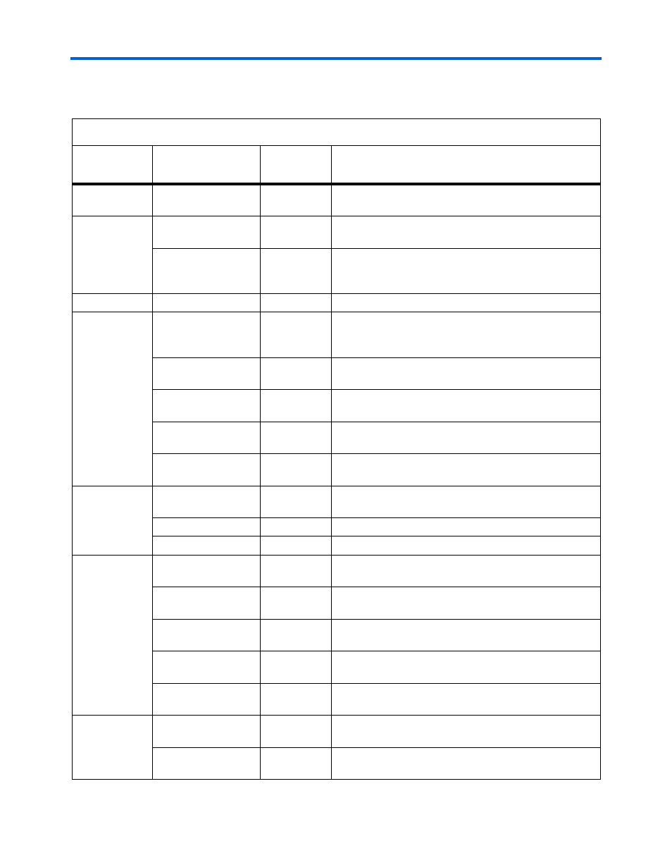
Table 2–1. Cyclone II EP2C35 PCI Development Board Components & Interfaces (Part 1 of 2)
Type
Component/
Interface
Board
Reference
Description
FPGA
Cyclone II device
U9
The EP2C35F672 device is installed on the board for the
PCI Development Kit, Cyclone II Edition.
PCI, PCI-X
PCI connector
J13
Universal PCI and PCI-X bus interfaces. Refer to
PCI level converters
U13 through
U17, U20
through U24
Level converters for 5.0-V PCI compatibility. Refer to
“PCI Level Converters” on page 2–4
.
Memory
DDR2 SDRAM
U6, U10
167 MHz, 32-MByte DDR2 SDRAM
Configuration
User and local-serial
FLASH memory
U7, U19
Switch-selectable, factory-programmed (safe) EPCS64
or user-programmable EPCS64 for Cyclone II device
configuration.
JTAG connector
J8
JTAG test and control as well as USB-Blaster
configuration interface.
Active serial (AS)
connector
J11
AS configuration interface for EPCS64 device
programming (may not be installed).
Configuration status
LED
D10 (bottom)
(red)
Indicates reconfiguration in progress or configuration
error.
Configuration done
LED
D10 (top)
(green)
Indicates Cyclone II configuration is complete.
Clock
High-speed clock
oscillator
Installed at
J9
100-MHz high-speed reference clock.
SMA clock
J5
Clock input.
Ethernet clock
OSC1
25-MHz Ethernet clock
Control
User reset push-
button switch
S3
User-defined hardware reset.
Reconfigure push-
button switch
S2
Reconfigure Cyclone II device.
PCI Mode
DIP switch
S4,
position 1
Enables PCI-X extensions. See
PCI XSPD
DIP switch
S4,
position 2
If enabled, selects PCI-X operating speed (i.e., 66 or
133 MHz). See
PCI SPD
DIP switch
S4,
position 3
Selects PCI bus operating speed (66 or 33 MHz). See
User settings
User push-button
switches
S1, S5
User configurable.
User DIP switch bank S4,
positions 4-8
User configurable, 5 switches.