External power jack, Test points – Altera Cyclone II EP2C35 PCI Development Board User Manual
Page 18
2–8
Core Version 4.0.0
Altera Corporation
Cyclone II EP2C35 PCI Development Board Reference Manual
May 2005
Component Operation
External Power Jack
Board header J2 is a power receptacle from a standard laptop power
supply.
Table 2–8
shows that the external power switch (SW1) enables the
external power supply.
1
If both the external power and the PCI power are supplied at the
same time, the board draws power from the external power
supply for all power rails except the 5.0-V power rail. Therefore,
when the PCI 3.3-V circuit transistors detect external power
supply voltage, they disable the power from the PCI connector.
The external power switch does not control the power from the
PCI connector.
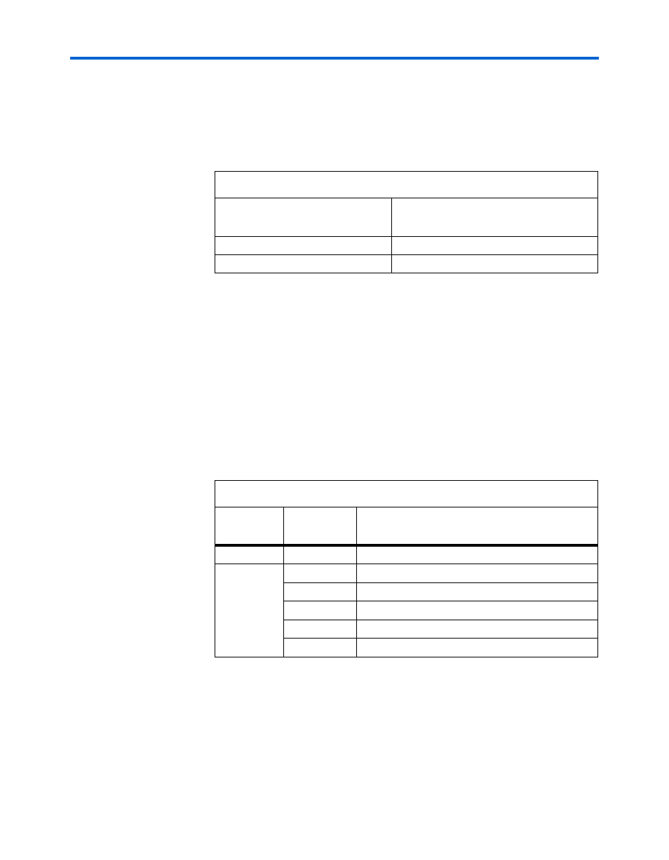
Test Points
Table 2–9
shows the board’s power supply test points.
Table 2–8. External Power Supply Enable
External Power Switch (SW1)
Position (PWR SWITCH)
Description
Off
Disable external power supply
On
Enable external power supply
Table 2–9. Board’s Power Supply Test Points
Signal
Name
Reference
Designator
Description
VREF
TP4
0.9-V VREF for DDR2 SDRAM
Ground
TP5
Ground test point near oscillator socket.
TP1
Ground test point near power connector.
TP2
Ground test point near PWR SWITCH.
TP3
Ground test point near MICTOR.
TP6
Ground test point near DDR2 SDRAM.