Control & user settings, User leds, Dip switch bank board & user settings – Altera Cyclone II EP2C35 PCI Development Board User Manual
Page 47: Control & user settings –13
Altera Corporation
Core Version 4.0.0
4–13
May 2005
Cyclone II EP2C35 PCI Development Board Reference Manual
Pin-Outs & Signal Specifications
Control &
User Settings
This section describes pin-outs and signal specifications for:
■
User LEDs
■
DIP switch bank board & user settings
■
Push-button switches
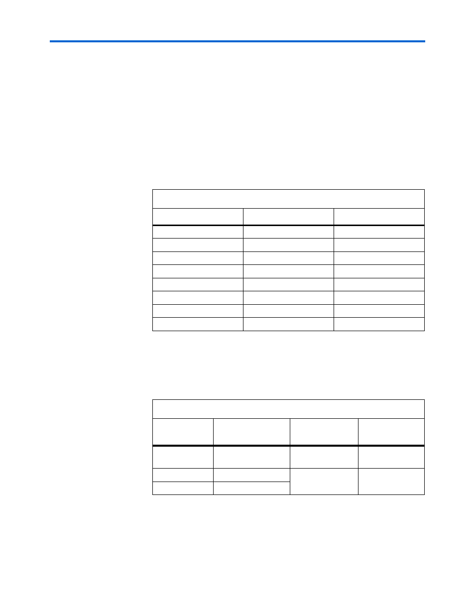
User LEDs
The Cyclone II device directly drives signals USER_LED0 through
USER_LED7
. See
Table 4–10
. To illuminate the LED, set the control signal
to logic 0.
DIP Switch Bank Board & User Settings
Table 4–11
lists the DIP switch bank (S4) board settings and the
corresponding board references, signal names, and destinations.
Table 4–10. User LED Connections
Label
Reference Designator
Cyclone II Pin (U9)
0
D8
J22
1
D7
K19
2
D6
K21
3
D5
M21
4
D4
L23
5
D3
L19
6
D2
K24
7
D1
T21
Table 4–11. DIP Switch Bank Board Settings
Board
Reference
DIP Switch Bank
Board Settings
Signal Destination
PCI SPD
Switch S4 Position 3
PCI_M66EN
PCI Connector
J13.B49
PCI Mode
Switch S4 Position 1
PCI_XCAP
PCI Connector
J13.B38
PCI XSPD
Switch S4 Position 2