As interface header, Epcs64 serial flash interface – Altera Cyclone II EP2C35 PCI Development Board User Manual
Page 46
4–12
Core Version 4.0.0
Altera Corporation
Cyclone II EP2C35 PCI Development Board Reference Manual
May 2005
Configuration
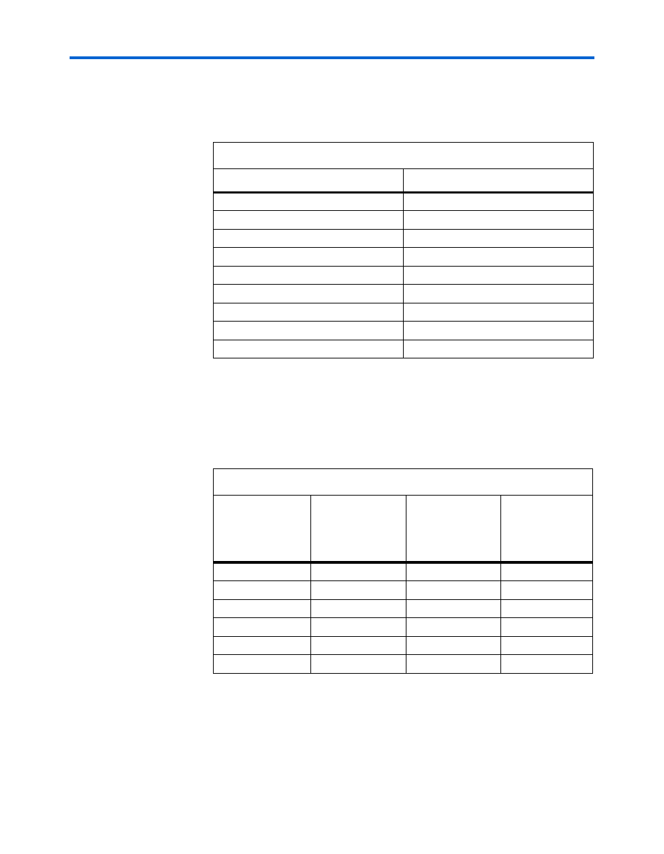
AS Interface Header
Table 4–8
shows the AS interface header connections.
EPCS64 Serial Flash Interface
Table 4–9
shows the EPCS64 serial flash interface signal and pin
connections for both the user-programmable and preloaded,
factory-programmed serial flash devices.
Table 4–8. AS Interface Header Connections
AS Signal
AS Connector (J8)
CONF_DCLK
1
CONF_DONE
3
CONF_CONFIGn
5
CONF_DATA0
7
CONF_ASD0
9
CONF_CEn
6
CONF_CS0n
8
GND
2, 10
3.3V
4
Table 4–9. EPCS64 Serial Flash Interface Connections
EPCS64 Serial
Flash Signal
User-
Programmable
EPCS64 Device
(U7)
Factory-
Programmed
EPCS64 Device
(U19)
Cyclone II Pin
(U9)
CONF_DCLK
16
16
N6
CONF_DATA0
8
8
N3
CONF_ASD0
15
15
E3
CONF_CS0n
–
–
D3
CONF_USER_CS0n
7
–
G18
CONF_SAFE_CS0n
–
7
G17