Altera Cyclone II EP2C35 PCI Development Board User Manual
Page 38
4–4
Core Version 4.0.0
Altera Corporation
Cyclone II EP2C35 PCI Development Board Reference Manual
May 2005
PCI & PCI-X Bus Interfaces
shows the PCI system configuration signals.
PCI_AD45
B81
F25
LPCI_AD45
PCI_AD46
A80
F26
LPCI_AD46
PCI_AD47
B80
G21
LPCI_AD47
PCI_AD48
A79
G22
LPCI_AD48
PCI_AD49
B78
G23
LPCI_AD49
PCI_AD50
A77
G26
LPCI_AD50
PCI_AD51
B77
H23
LPCI_AD51
PCI_AD52
A76
H25
LPCI_AD52
PCI_AD53
B75
H26
LPCI_AD53
PCI_AD54
A74
J20
LPCI_AD54
PCI_AD55
B74
J21
LPCI_AD55
PCI_AD56
A73
J23
LPCI_AD56
PCI_AD57
B72
J24
LPCI_AD57
PCI_AD58
A71
J25
LPCI_AD58
PCI_AD59
B71
J26
LPCI_AD59
PCI_AD60
A70
K22
LPCI_AD60
PCI_AD61
B69
K23
LPCI_AD61
PCI_AD62
A68
K25
LPCI_AD62
PCI_AD63
B68
K26
LPCI_AD63
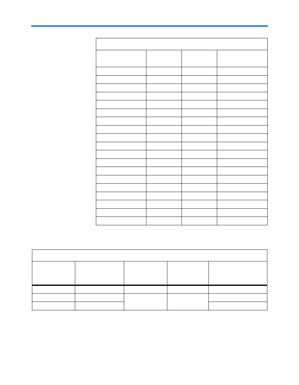
Table 4–1. PCI Signals & Connections (Part 4 of 4)
PCI Signal
PCI Connector
(J13)
Cyclone II Pin
(U9)
Local Signal
Table 4–2. PCI System Configuration Signals
Board Reference
Board Settings DIP
Switch Bank
Positions (S4)
PCI Signal
PCI Connector
(J13)
Attribute
PCI SPD
Switch S4, position 3
PCI_M66EN
B49
Ground
PCI Mode
Switch S4, position 1
PCI_XCAP
B38
Ground
PCI XSPD
Switch S4, position 2
10-K
Ω resistor to ground