Push-button switches – Altera Cyclone II EP2C35 PCI Development Board User Manual
Page 48
4–14
Core Version 4.0.0
Altera Corporation
Cyclone II EP2C35 PCI Development Board Reference Manual
May 2005
Control & User Settings
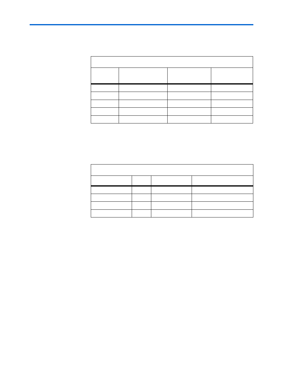
Table 4–12
shows the user DIP switch bank (S4) signal names, board
references, and pin connections.
Push-Button Switches
Table 4–13
shows the push-button switch signal names and pin
connections.
Table 4–12. User DIP Switch Bank Settings
Board
Reference
User DIP Switch
Signal
Cyclone II Pin (U9)
0
Switch S4 Position 4
USER_SW0
AA12
1
Switch S4 Position 5
USER_SW1
AB8
2
Switch S4 Position 6
USER_SW2
AC6
3
Switch S4 Position 7
USER_SW3
AD12
4
Switch S4 Position 8
USER_SW4
AD8
Table 4–13. Push-Button Switch Signal Names & Pin Connections
Board Reference
Pin
Signal
Cyclone II Pin (U9)
RESET
S3.2
SYS_RESETn
C5
RECONFIG
S2.2
CONFIG_PBn
R23 (through diode U18)
PB0
S1.2
USER_PB0n
B12
PB1
S5.2
USER_PB1n
D13