Push-button switches – Altera Cyclone II EP2C35 PCI Development Board User Manual
Page 23
Altera Corporation
Core Version 4.0.0
2–13
May 2005
Cyclone II EP2C35 PCI Development Board Reference Manual
Board Components & Interfaces
Push-Button Switches
Table 2–15
describes the board’s push-button switches.
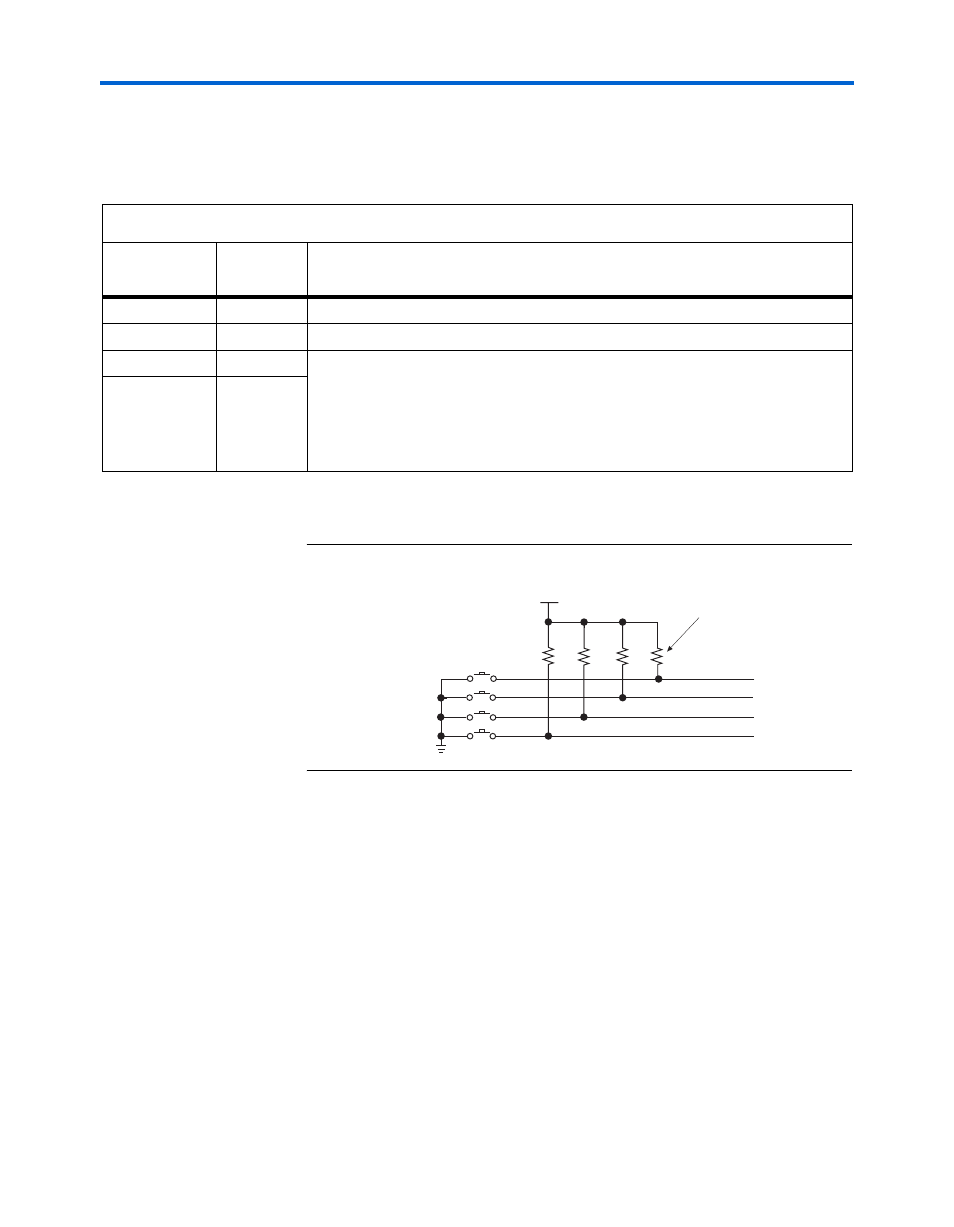
shows the board’s push-button switch circuitry.
Figure 2–3. Board Push-Button Switches
Table 2–15. Push-Button Switches
Board
Reference
Reference
Designator
Description
RECONFIG
S2
Causes Cyclone II device to reload configuration
RESET
S3
User-defined hardware reset.
PB0
S1
User-defined. These switches are momentary-contact, push-button switches that
provide stimulus to designs in the Cyclone II device. Each switch is connected to
a Cyclone II general purpose I/O pin with a pull-up resistor. When a switch is
pressed, the Cyclone II device pin will detect a logic 0; when the switch is not
pressed, the Cyclone II device pin will detect a logic 1. The push-button switches
are tied high with a pull-up resistor.
PB1
S5
3.3 V
1
1
1
1
2
2
2
2
S2
S3
S5
S1
RECONFIG
RESETn
USER PB1n
USER PB0n
R35
10K
Ω resistors
R40
R33
R34