Board dip switch settings – Altera Cyclone II EP2C35 PCI Development Board User Manual
Page 21
Altera Corporation
Core Version 4.0.0
2–11
May 2005
Cyclone II EP2C35 PCI Development Board Reference Manual
Board Components & Interfaces
Board DIP Switch Settings
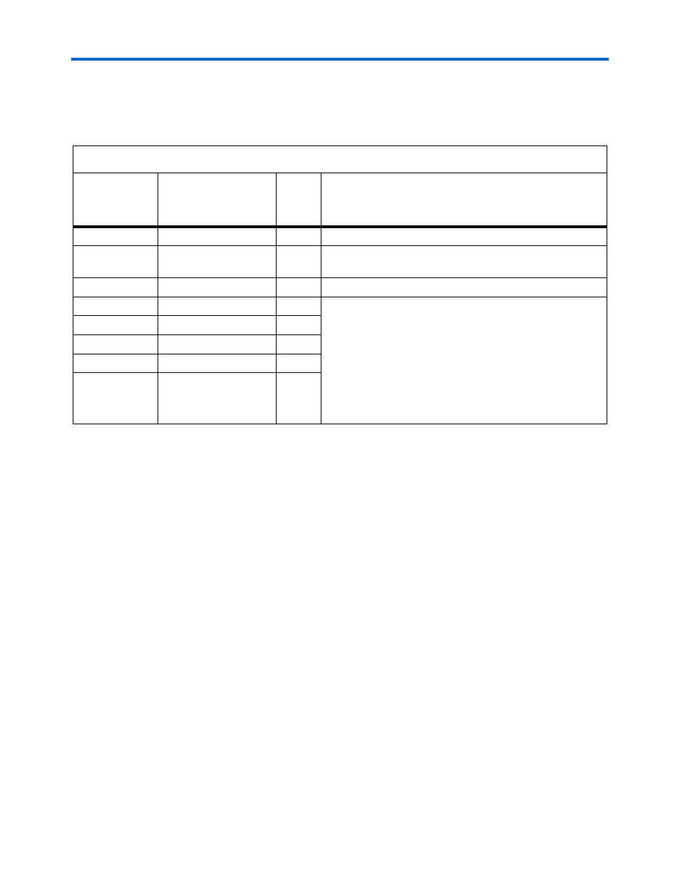
Table 2–14
describes the board DIP switch bank (S4) settings.
Table 2–14. Board DIP Switch Settings
Board
Reference
Board DIP Switch
Settings
Factory
Default
Setting
Description
PCI XSPD
Switch S4 Position 2
On
Selects PCI-X bus operating speed. Refer to
PCI MODE
Switch S4 Position 1
On
Toggles between PCI and PCI-X operating modes. Refer to
PCI SPD
Switch S4 Position 3
Off
Selects PCI bus operating speed. Refer to
User SW0
Switch S4 Position 4
Off
User defined. These DIP switches are directly connected to
the Cyclone II device. These switches are momentary-
contact, push-button switches that provide stimulus to
designs in the Cyclone II device. Each switch is connected
to a Cyclone II general purpose I/O pin with a pull-up
resistor. When a switch is pressed, the Cyclone II device
pin will detect a logic 0; when the switch is not pressed, the
Cyclone II device pin will detect a logic 1. The push-button
switches are tied high with a pull-up resistor.
User SW1
Switch S4 Position 5
Off
User SW2
Switch S4 Position 6
Off
User SW3
Switch S4 Position 7
Off
User SW4
Switch S4 Position 8
Off