CIRCUTOR CVM144 Series User Manual
Page 57
----- Supply network analyzer CVM-144 ------ User's manual --- Page No. 56
13.- APPENDIX B: Insertion of an expansion module into a CVM-144 unit
The installation of an extension card into a CVM-144 unit must be accomplished just
following below enumerated steps:
Checking the card acknowledgement
1. Check that the expansion card to be inserted into the CVM-144 will be
acknowledged by the power meter.
Code
Expansion module
Board
5.xx
6.xx
7 70 570 Mod. CVM 144 C2
x
7 70 571 Mod. CVM 144 C2 Analogue
0571
x
x
7 70 572 Mod. CVM 144 C2-Currents
0572
x
7 70 569 Mod. CVM 144 C2-Digital
x
7 70 573 Mod. CVM 144 RS485-C2
0573
x
x
7 70 574 Mod. CVM 144 RS485-C2-Analogue
0574
x
x
7 70 575 Mod. CVM 144 RS485-C2-Currents
0575
x
7 70 579 Mod. CVM 144 RS485-C2-Digital
0579
x
x
7 70 576 Mod. CVM 144 RS232-C2
0576
x
x
7 70 577 Mod. CVM 144 RS232-C2 Analogue
0577
x
x
7 70 578 Mod. CVM 144 RS232-C2-Currents
0578
x
7 70 580 Mod. CVM 144 RS232-C2 Digital
0580
x
x
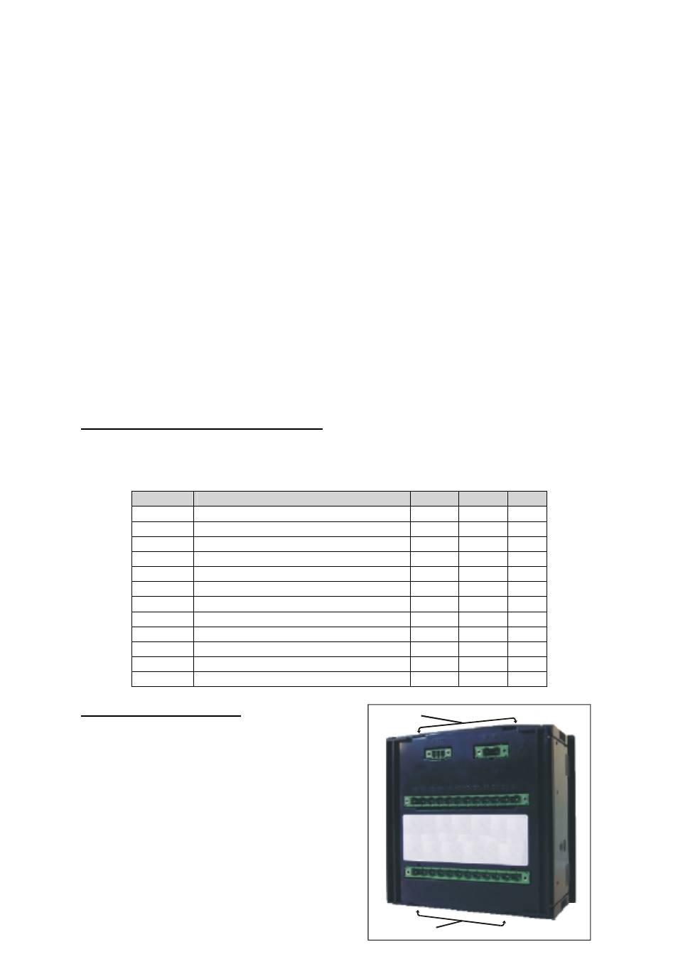
Removing the rear cover
2. Disconnect the meter out from the electric
network.
3. Pull the connection terminals out.
4. Insert a plain-edge screwdriver into the
bottom gaps (see right picture) and pull
up the holding pieces until these are
released.
5. Now, the cover should be easily
removable with the hand.
Ranuras
Ranuras