No. terminal description – CIRCUTOR CVM144 Series User Manual
Page 9
----- Supply network analyzer CVM-144 ------ User's manual --- Page No. 8
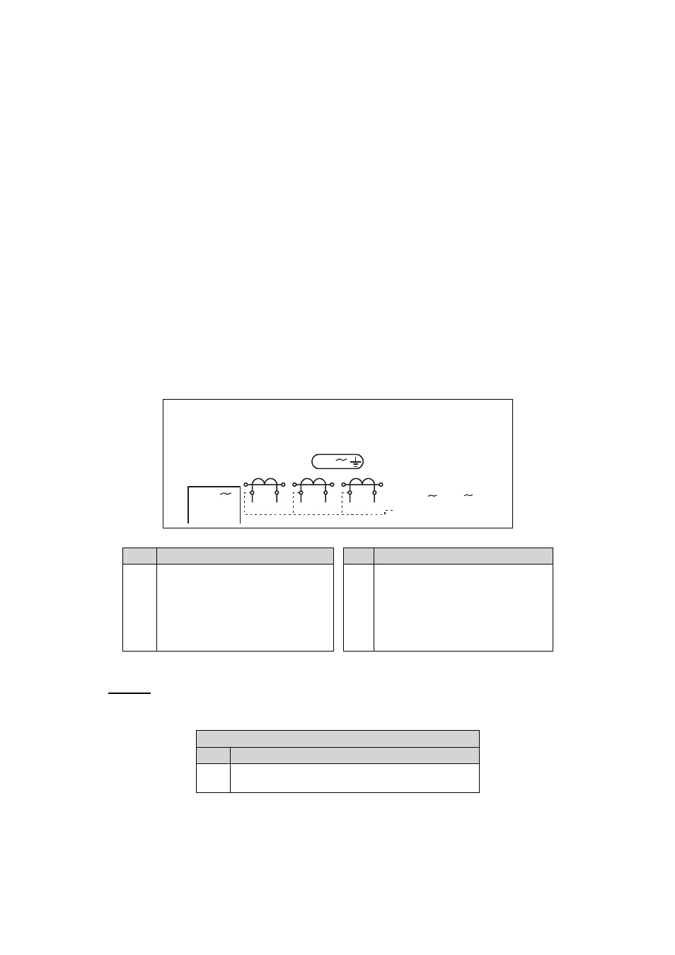
4.2.- CVM-144 connection terminal arrangement (power supply connection terminal)
(see lable on the rear part)
9
1
2
5
6
7
8
3
4
10
11
12
S2
S1
S2
S1
S2
S1
L1
P2
P1
L2
P2
P1
L3
P2
P1
Power Supply
230 V
N
L1
V
L2
V
V
L3
CA
T
III
300V
P-N
P-P
520V
I
n
/
5A
300 V
No. Terminal description
No. Terminal description
1
2
3
4
5
6
*Power supply AL1
*Power supply AL2
IL1 S2 Current measurement
IL1 S1 Current measurement
IL2 S2 Current measurement
IL2 S1 Current measurement
7
8
9
10
11
12
IL3 S2 Current measurement
IL3 S1 Current measurement
Neutral
VL1 Measurement
VL2 Measurement
VL3 Measurement
NOTE: Terminals 3, 5, 7 are internally connected to the 9 terminal (Neutral)
... / 5 A current inputs are isolated for the ITF model.
* Lower connection terminal (SDC Model)
Nº Descripción Borne
1
2
Supply voltage (+) d.c.
Supply voltage (-) d.c.