Adept Lynx Platform User Manual
Page 100
Adept Lynx Platform User's Guide, Rev B
Page 100 of 116
Chapter 8: Maintenance
5. Disconnect the cable from the light disc PCA, so the side cover can be moved com-
pletely away from the platform.
This will expose the drive assembly.
6. Lift the drive wheel up, compressing its springs, enough so that you can insert a Ø 6 x
10 mm (Ø 0.24 x 0.4 in.) pin into the hole on the rear side of the assembly (there is a
hole on each side). This will keep the springs compressed (the wheel will be in the up
position), and make removal easier. An M5 x 10 screw works well for this.
Figure 8-12. Spring-Compression Hole
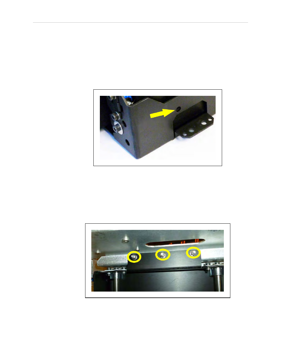
7. The drive assembly is held in place with three nuts on studs across the top, and two
sets of two screws at each side, near the bottom of the assembly.
Remove the three nuts and four screws (and their washers) holding the drive assembly
to the platform.
Retain these nuts, screws, and washers for attaching the new drive assembly.
Figure 8-13. Mounting Studs and Nuts at top of Drive Assembly