Lynx core rear, upper – Adept Lynx Platform User Manual
Page 54
Adept Lynx Platform User's Guide, Rev B
Page 54 of 116
Chapter 5: Connectivity
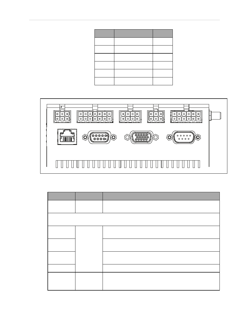
Pin No.
Designation
Notes
1, 4, 6, 9 No Connection
2
RS232_USR#_RXD #=1 or 2
3
RS232_USR#_TXD
#=1 or 2
5
GND
7
RS232_USR#_RTS
#=1 or 2
8
RS232_USR#_CTS
#=1 or 2
Lynx Core Rear, Upper
Light Pole
User Interface User Bumpers Aux Power
User Power
Maint LAN
Joystick
HMI Panel
Sonar 2
Figure 5-5. Rear Upper Core
Connection
Type
Description
Light Pole
Mini-Fit2 x 3
Connects to a user-supplied light tower with 3 lights and 1
buzzer, using a default configuration
NOTE: The following four functions are pins on the User Interface connector.
Brake-
release
Mini-Fit 2 x 7
Pins for user-supplied brake release
ON
Pins for user-supplied ON button; same function as Operator
Panel ON
OFF
Pins for user-supplied OFF button; same function as Operator
Panel OFF
ESTOP
Pins for user-supplied E-Stop
User Bump-
ers
Mini-Fit 2 x 4
Payload bumpers, user-supplied, connected between ESTOP_
SRC and USER_BMP# (for each of the 6 inputs).
Contacts should be 12 V @ 10 mA.