ONICON F-1100 Series User Manual
Page 19
11451 Belcher Road South, Largo FL 33773 • USA • Tel +1 (727) 447-6140 • Fax (727) 442-5699 • [email protected]
Turbine Flow Meter Manual 05/14 - 0721-3 / 13518
Page 19
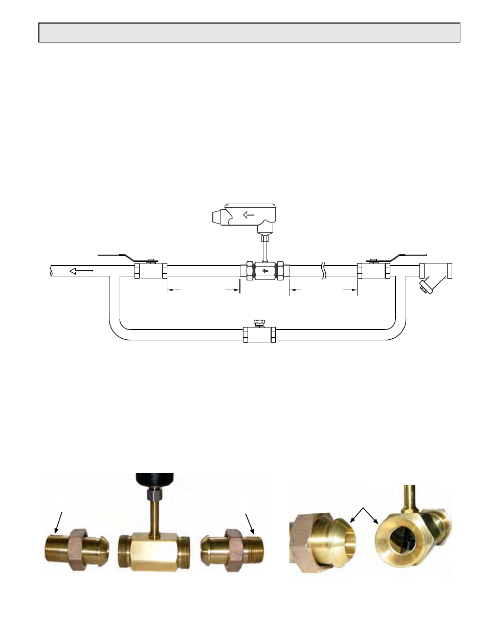
3.6 INLINE METER STRAIGHT RUN REQUIREMENTS AND MECHANICAL INSTALLATION
Locating the meter
1. Install process connections (sweat or threaded end pieces) making certain to leave adequate
straight unobstructed pipe runs upstream and downstream of the meter location.
a. The minimum upstream straight run should be at least 20 diameters and the downstream
straight run should be at least 5 diameters in length.
b. If more than 25 diameters of straight run are available at the installation site the excess
straight run should be upstream of the meter location.
c. Please note that ONICON strongly recommends the use of strainers upstream of the meter
location.
d. ONICON also recommends the installation of isolation valves and a bypass loop to
accommodate servicing the meter.
Isolation Valve
Normally Open
5 Dia. Minimum
Straight Run
Downstream
Isolation Valve
Normally Open
Bypass Valve
Normally Closed
20 Dia. Minimum
Straight Run
Upstream
y-Strainer
Upstream of
Flow Meter
Installing the meter body
1. Make sure the unions are free of nicks or scratches on either end of the flow
meter body and on the process connections.
2. Spray the union faces with a silicone spray or apply a thin coat of beeswax to enhance
seating. Do not use paste thread sealant on union faces.
3. Recommended torques for union seal: 70 ft/lbs minimum
4. Make sure alignment of pipe does not put lateral stress on either joint.
TYPICAL INLINE METER INSTALLATION
Process
Connection
Process
Connection
Unions