ONICON F-1100 Series User Manual
Page 42
11451 Belcher Road South, Largo FL 33773 • USA • Tel +1 (727) 447-6140 • Fax (727) 442-5699 • [email protected]
Turbine Flow Meter Manual 05/14 - 0721-3 / 13518
Page B-3
11451 Belcher Road South, Largo, FL 33773 • USA • Tel +1 (727) 447-6140 • Fax (727) 442-5699
www.onicon.com • [email protected]
05-14
0540-2 / 15951
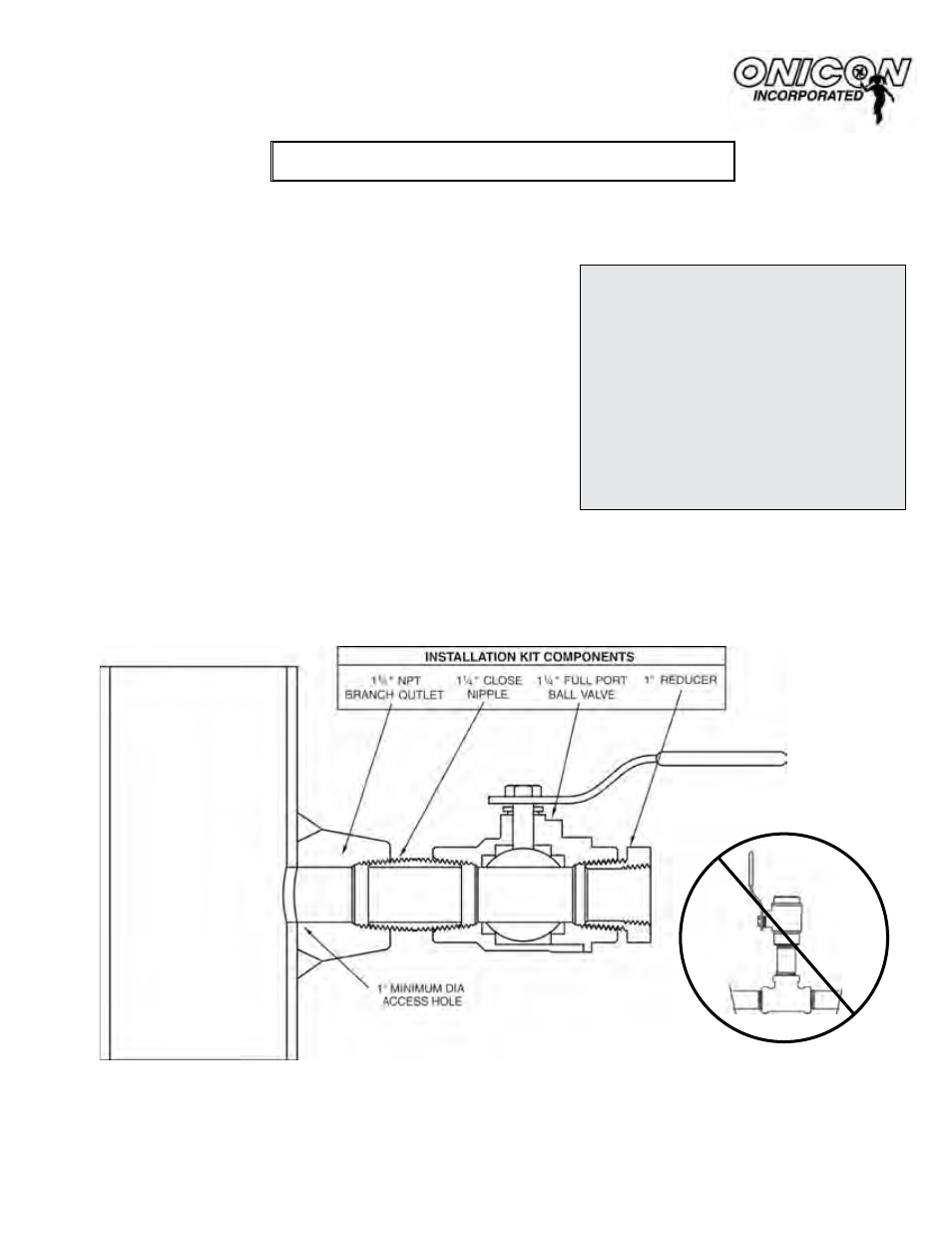
Do not substitute threaded tees for
the welded branch outlet. Contact
ONICON if you need installation
hardware for threaded pipe.
Installation Hardware Instructions
Hot Tap Installation Kit for Welded Steel Pipe
For F-1100, F-1200 & FB-1200 Series Insertion Turbine Flow Meters
This kit can be installed on a pressurized pipe. A hot tap drilling machine is used to create a one
inch opening in the pipe wall. Once installed, this kit allows for insertion and removal of the flow
meter without a system shutdown.
For Use With Kits: INSTL2, INSTL6, INSTL31
Directions:
1. Identify an appropriate location for the flow
meter (see pages 2-4).
2. Weld the branch outlet onto the pipe.
3. Install the close nipple and ball valve as shown
below. Use a paste type thread sealant. DO
NOT use Teflon® tape.
4. Use a hot tap drilling machine with a 1” hole
saw to drill the access hole.
5. Remove the drill; then flush all debris out of
the valve.
6. Use the 1” reducer provided in this kit when
installing the flow meter
NOTE: Before installing the flow meter, read the entire
installation manual.
Important Note
ONICON insertion flow meters
are precision measuring devices
that must be installed according to
the instructions contained in this
document in order to maintain their
accuracy and reliability. Failure to
follow these instructions will result
in erratic operation and reduced
accuracy.
(see Sections 3.1 and 3.2).