ONICON F-1100 Series User Manual
Page 6
11451 Belcher Road South, Largo FL 33773 • USA • Tel +1 (727) 447-6140 • Fax (727) 442-5699 • [email protected]
Turbine Flow Meter Manual 05/14 - 0721-3 / 13518
Page 6
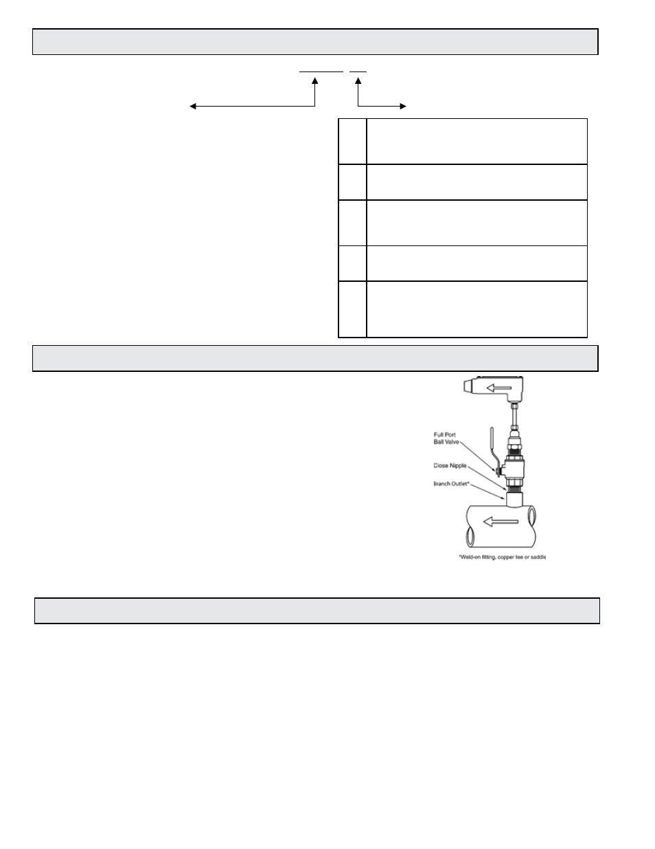
1.5 ADDITIONAL REQUIRED HARDWARE
All ONICON insertion type meters can be installed and removed
via a 1” or larger full port ball valve without stopping flow. The
terms “Standard” and “Hot Tap” refer to the installation method
of the isolation valve kit only.
Standard Installation Hardware: For new construction or
scheduled shutdown; once kit is installed, the flow meter can be
installed or removed without system shutdown.
Hot Tap Installation Hardware: For applications which require
the access hole in the pipe to be drilled through the valve
using a wet tap drilling machine, while the hydronic system is
pressurized and operating.
NOTE: Installation hardware materials vary greatly based on pipe
material, pipe size and standard vs. hot tap versions.
1.4 MODEL NUMBERING SYSTEM
F(B)-XX YY
SERIES
OUTPUT SIGNAL
F-11
Single Turbine, Insertion Type
F-12
Dual Turbine, Insertion Type
FB-12 Bi-Directional, Insertion Type
F-13
Inline Turbine Meter
Example:
“F-1210” = Dual turbine, analog output
00
Frequency Output (15 V pulse)
For connection to ONICON display or BTU meter
only. Signal is too fast for most building control
systems (0-500 Hz).
10
Analog Output (non-isolated) Provides both 4-20 mA
and 0-10 V outputs. Most commonly used output
type. (3-wire connection)
11
Isolated Analog Output
Provides both 4-20 mA and 0-10 V outputs. Signal
ground is isolated from power supply and pipe
ground. (4-wire connection)
20
Divided Output (Solid state dry contact) Provides an
isolated binary/digital output. Signal is divided to
limit the maximum frequency. For rate/totalization.
30
Scaled Output (Solid state dry contact)
Provides an isolated binary/digital output scaled to
provide one pulse per desired unit volume (e.g.: 1
pulse = 10 gal.).
Ideal for totalization applications.
1.6 WARRANTY AND SERIAL NUMBER
Warranty
ONICON’s complete warranty is included in Appendix C of this manual as a part of the
“Conditions of Sale.” Meters purchased after November 1, 2000 include a two-year “No fault”
warranty which may cover accidental damage caused during installation or start up.
Serial Number
The serial number of your flow meter is located on a label on the side of the electronics enclosure.
The model number is also listed on this label. The serial number is a unique identifier that you
should refer to, along with the model number, whenever you contact ONICON for assistance
regarding your meter.