Evaluating upstream piping conditions – ONICON F-1100 Series User Manual
Page 9
11451 Belcher Road South, Largo FL 33773 • USA • Tel +1 (727) 447-6140 • Fax (727) 442-5699 • [email protected]
Turbine Flow Meter Manual 05/14 - 0721-3 / 13518
Page 9
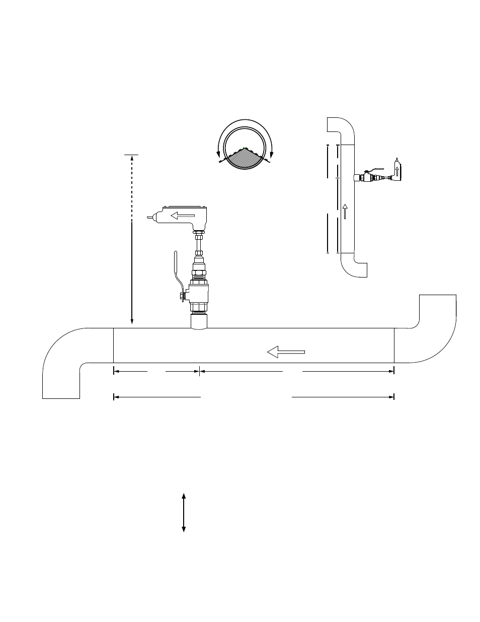
INSERTION AND INLINE FLOW METER SITE SELECTION
GENERAL GUIDELINES
(Shown with Insertion Meter)
• Install in vertical or horizontal pipe.
• For horizontal pipe position meter
anywhere in upper 240
˚.
FLOW
20%
80%
Upstream
Downstream
Available Straight Run*
23" - 36"
Depending on
pipe size
CLEARANCE
REQUIRED
FOR INSTALLATION
FLO
W
20%
80%
Upstream
Do
wnstream
A
v
ailab
le Str
aight Run*
Vertical pipe position
*See following pages for model specific straight run requirements.
EVALUATING UPSTREAM PIPING CONDITIONS
Straight Pipe
Single Bend
Pipe Reduction or Enlargement
Outflowing Tees
Multiple Bends in Same Plane
Multiple Bends Out of Plane
Inflowing Tees
Control Valves
W
orse
Better
CLEARANCE
REQUIRED
FOR INSTALLATION
23” - 36”
Depending on
pipe size
Allow at least
6” for inline meters
(Downward flow is also allowed)